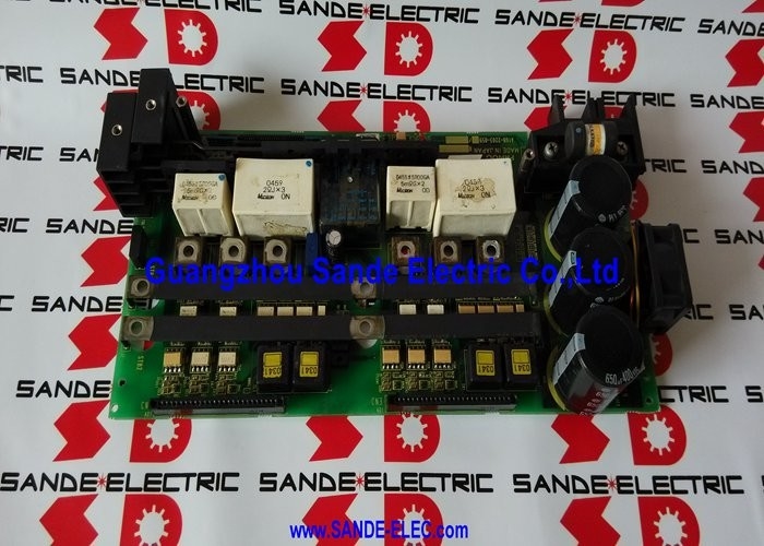
A16B-2203-0590 | FANUC Alpha SVM2-12/40 Wiring Board — Type A and FSSB Interface / A06B-6079-H204 / A06B-6096-H204 / Supersedes A16B-2202-0770
SVM2-12/40 — Asymmetric Twin-Axis Drive
The FANUC Alpha SVM2-12/40 is a two-axis servo amplifier module with different current ratings per axis. Unlike the symmetric SVM2-12/12 (12A on both axes) or SVM2-40/40 (40A on both axes), the 12/40 configuration provides:
- 12A axis (lighter duty): For a lighter machine axis — tool turret, workpiece rotation, or an auxiliary axis with smaller servo motor requirement.
- 40A axis (heavier duty): For a heavier machine axis — typically the main translational axis with a larger motor and higher inertia requirement.
This asymmetric pairing allows a machine builder to closely match the servo amplifier current to each axis's actual demand. Installing a uniform 40/40 module where one axis only needs 12A wastes cost and cabinet space. The SVM2-12/40 is the engineering-optimal choice for machines with one light axis and one heavy axis.
Key Specifications
| Parameter |
Value |
| Module |
SVM2-12/40 (2-axis) |
| Interface |
Type A and FSSB |
| Type A Module |
A06B-6079-H204 |
| FSSB Module |
A06B-6096-H204 |
| Supersedes |
A16B-2202-0770 |
| Role |
Wiring board (main structural board) |
Type A and FSSB — One Wiring Board for Both Interfaces
The A16B-2203-0590 serves the SVM2-12/40 in both its interface variants:
Type A interface (A06B-6079-H204): The serial servo bus interface using a dedicated cable from the CNC. Earlier interface generation, still common on Series 15 and early i-series systems.
FSSB interface (A06B-6096-H204): The fibre optic servo bus interface used on i-series CNC systems. Provides immunity to electromagnetic noise from the drive cabinet.
The wiring board's physical connector set accommodates both interface types because the mechanical board dimensions and motor/bus connector layout are common across Type A and FSSB SVM2-12/40 variants. Only the control PCB and the servo bus connector differ between the two.
Application Scenarios
SVM2-12/40 wiring board fault: A FANUC Alpha servo module develops alarm codes affecting both axes. The control PCB tests correctly, but inspection reveals damaged high-current motor connector traces on the wiring board. The A16B-2203-0590 replacement restores the module's connector integrity and both axis servo functions.
Module refurbishment: An Alpha SVM2-12/40 module undergoes workshop refurbishment. The A16B-2203-0590 wiring board is replaced alongside the control PCB to provide a complete internal board refresh.
FAQ
Q1: Can the A16B-2203-0590 be used in an FSSB-interface SVM2-12/40 and also a Type A SVM2-12/40?
Yes. The FANUC Alpha maintenance manual confirms A16B-2203-0590 as the wiring board for both A06B-6079-H204 (Type A) and A06B-6096-H204 (FSSB) modules. The wiring board is the common structural element for both interface variants. The CNC servo interface connector on the wiring board accepts both Type A cable and FSSB fibre optic connector, or the interface-specific connection is made through the control PCB's connector rather than the wiring board.
Q2: What is the control PCB that pairs with the A16B-2203-0590 in the SVM2-12/40?
For the HRV3 control configuration (higher-performance current control): the wiring board A16B-2203-0590 pairs with the control PCB A20B-2100-0541 (FSSB interface). For standard configurations, the pairing depends on the module generation. The FANUC Alpha Series maintenance manual table specifies: "When using HRV3, use the following boards together: Wiring board: A16B-2203-059X / Printed circuit board: A20B-2100-054X."
Q3: Why does the SVM2-12/40 use asymmetric current ratings rather than a uniform 40/40?
Current-matched drive configuration reduces cost and improves thermal management. A 40A output stage for a 12A axis wastes approximately 30A of rated capacity, adding cost in IGBT devices, cooling, and cabinet size. The SVM2-12/40 provides each axis exactly the current it needs. This is particularly useful on CNC lathes where the Z-axis (carriage) carries higher load than the X-axis (cross-slide), or on machines where one axis is a lightweight auxiliary rather than a main cutting axis.
Q4: After fitting a replacement A16B-2203-0590, do encoder or motor cables need to be re-routed?
The encoder and motor cable connectors on the wiring board maintain the same physical pinout and mechanical configuration as the original board. Cable connections are re-made to the same connector positions on the new board — no re-routing or modification to the machine wiring is required.
Q5: Can the A16B-2203-0590 wiring board be replaced without accessing the control PCB?
Within the SVM2-12/40 module housing, the control PCB mounts on top of the wiring board. To remove the wiring board, the control PCB must first be removed to expose the wiring board's retaining hardware. The two boards are separated inside the module. After replacing the A16B-2203-0590, the control PCB is reinstalled on the new wiring board before the module is closed and reinstalled in the drive cabinet.



 Your message must be between 20-3,000 characters!