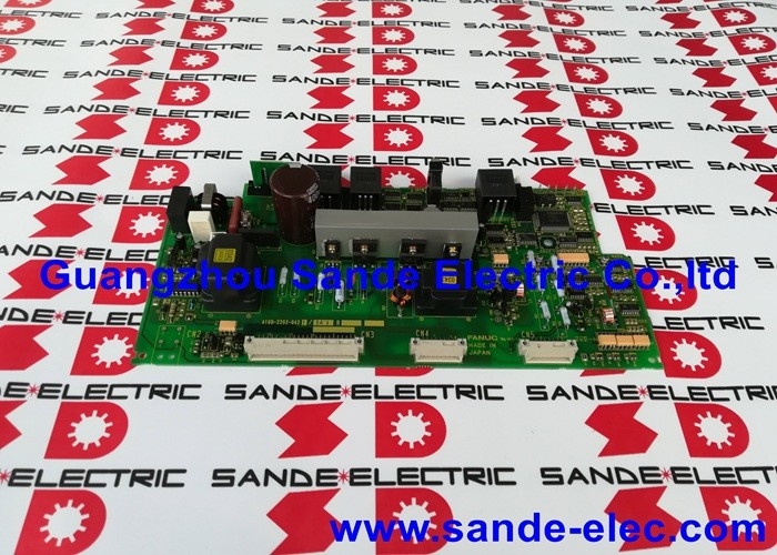
A16B-2202-0421 | FANUC Alpha PSM Servo Power Supply Control PCB — PSM-15 to PSM-55 / 200VAC / 283–325VDC Regenerative / DC Bus
PSM — The DC Bus Source for All Alpha Drives
In a FANUC Alpha series servo system, the drive cabinet contains three types of modules on a shared DC bus:
- PSM (Power Supply Module): Converts AC mains to the DC bus. All other modules draw from this bus.
- SVM (Servo Module): Drives servo motors from the DC bus.
- SPM (Spindle Module): Drives the spindle motor from the DC bus.
The PSM is the electrical foundation of the entire drive system. No servo motor turns, no spindle runs, and no DC bus exists unless the PSM is functioning correctly.
The A16B-2202-0421 is the control PCB inside the PSM. It manages the rectification and power factor correction circuits, monitors the DC bus voltage, executes the power shutoff sequence on command or alarm, and handles the regeneration function — returning motor braking energy from the DC bus back to the AC mains supply.
Key Specifications
| Parameter | Value |
|---|
| Input | 200–230VAC, 3-phase, 50/60Hz |
| DC Bus Output | 283–325VDC |
| Compatible PSM | PSM-15 to PSM-55 |
| Power Type | Regenerative |
| Family | FANUC Alpha series |
PSM Alarm Codes
The PSM generates alarm codes that the CNC displays when a fault occurs. The A16B-2202-0421 monitors and reports these conditions:
- AL-01: Overcurrent in the main power module
- AL-02: Cooling fan stopped
- AL-03: Heatsink temperature abnormally high
- AL-04: DC bus voltage dropped
- AL-05: Main capacitor not recharged within specified time
- AL-06: Input power supply abnormal
- AL-07: DC bus voltage abnormally high
Application Scenarios
PSM alarm diagnosis: A FANUC Alpha drive system generates a persistent AL-04 (DC voltage drop) alarm after power-on. The AC input supply is confirmed correct, and the main power stage (wiring board and power devices) tests as intact. The A16B-2202-0421 control board is identified as the fault source. Replacement restores the PSM's DC bus voltage regulation.
Drive system maintenance overhaul: During a scheduled overhaul of an Alpha series drive cabinet, the A16B-2202-0421 is replaced as part of a proactive PCB renewal to prevent age-related PSM control board failures on a high-duty-cycle production system.
FAQ
Q1: If the PSM shows an AL-07 alarm (DC bus overvoltage), does this always indicate a control board fault?
AL-07 can have several causes: a control board fault, a failed regeneration circuit preventing the energy from returning to the grid, or a sudden high-inertia deceleration event that momentarily exceeds the regeneration capacity. Verify that the deceleration ramps in the CNC parameters are not set too aggressively before replacing the A16B-2202-0421. If the alarm occurs at normal deceleration rates, the control board or power stage is the likely fault source.
Q2: Can the A16B-2202-0421 be used with the BM-suffix PSM models (e.g., A06B-6087-H115#BM)?
The #BM suffix indicates a CE-marked variant of the PSM module. The corresponding control PCB for these CE-marked variants is the A16B-2202-0424, not the A16B-2202-0421. These two board versions are specific to their respective module variants and are not interchangeable. Confirm whether the installed PSM is the standard or BM variant before ordering the replacement control board.
Q3: What is the wiring board, and does it need to be replaced at the same time as the A16B-2202-0421?
The PSM contains two main PCBs: the control board (A16B-2202-0421) and the wiring board (the A20B-1006-xxxx variant specific to the PSM power rating). The wiring board handles the high-current power connections; the control board manages the regulation and protection logic. Unless the wiring board has visible damage — burn marks, failed components, damaged connectors — only the A16B-2202-0421 control board needs to be replaced in a control board failure.
Q4: Is it safe to test the A16B-2202-0421 by powering the PSM without any SVM or SPM modules connected?
The PSM can establish a DC bus without load modules connected. This is a valid isolation test to verify PSM function before reconnecting drive modules. However, the DC bus capacitors will charge to 283–325VDC. Observe all high-voltage safety precautions: never touch DC bus terminals or internal components with the unit powered. After powering down, wait for the capacitor discharge cycle (typically 5–10 minutes) before accessing the PSM interior.
Q5: How does the A16B-2202-0421 interact with the CNC during a controlled shutdown sequence?
The CNC sends a power shutoff command to the PSM via the servo enable signal before cutting AC power in a controlled shutdown. The A16B-2202-0421 responds by commanding the power stage to stop regeneration, allow the DC bus to discharge to a safe level through a controlled impedance path, and then switch off. This sequencing prevents abrupt DC bus voltage collapse that could corrupt drive parameters or cause mechanical issues from sudden axis power loss.

 Your message must be between 20-3,000 characters!