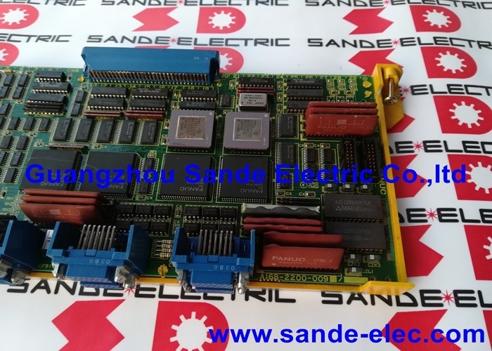
A16B-2200-0090 | FANUC Series 15-A 4-Axis Control PCB — Type A Interface / PWM Drive Output / 6058 / 6066 Servo / 15-MA / 15-TA
Series 15-A — FANUC's High-Axis-Count CNC Platform
The FANUC Series 15-A (Model A) is the highest-capability CNC in FANUC's Generation 15 product family. Where other CNC systems of the same era target 3 to 5 axis machine tools, the Series 15-A is designed from the ground up for machines requiring many more axes — multi-pallet machining centres, multi-spindle turning centres, and large-scale flexible manufacturing systems.
The A16B-2200-0090 is the axis control board that makes this multi-axis capability possible within the Series 15-A. Each board provides 4 axis channels. Multiple boards can coexist in the same CNC, building the total axis count in groups of 4 up to the system's maximum.
Key Specifications
| Parameter |
Value |
| Axis Channels |
4 (per board) |
| Interface |
Type A |
| Drive Compatibility |
FANUC 6058, 6066 drives |
| Output Signal |
PWM servo commands |
| Maximum System Axes |
Up to 16 (with 4 boards) |
| Compatible Systems |
15-A, 15-MA, 15-TA, 15-MF, 15-TF, 150M |
PWM Output — How the Board Commands the Drives
The A16B-2200-0090 generates PWM (Pulse Width Modulated) signals as its axis command output. Each of the board's 4 axis channels sends a PWM stream to the corresponding servo drive. The PWM signal encodes the velocity or torque command for that axis — the servo drive's power stage converts this PWM reference into the three-phase motor current that drives the axis motor.
The board reads position commands from the Series 15-A CNC's BASE command registers — shared memory locations where the main CPU writes position increments each interpolation cycle. The A16B-2200-0090 reads these commands and generates the appropriate PWM outputs to all four connected axes simultaneously, maintaining the synchronisation required for coordinated multi-axis motion.
Up to 16-Axis Scalability
One A16B-2200-0090 board covers 4 axes. For machines requiring more:
- 8 axes: Two A16B-2200-0090 boards — second board handles axes 5–8
- 12 axes: Three boards
- 16 axes: Four boards — the maximum configuration for the Series 15-A
In multi-board configurations, each board operates independently on its assigned axes. A fault on one board affects only its 4 axes — the remaining boards continue operating normally.
Application Scenarios
15-MA machining centre axis board fault: A Series 15-MA machining centre develops servo alarms on axes 1–4. The drives and motors test correctly. The A16B-2200-0090 axis board serving those axes is identified as the fault source. Board replacement restores all four axes.
16-axis transfer machine maintenance: A 16-axis machine uses four A16B-2200-0090 boards. One board fails, affecting only its four axes. The failed board is replaced without disrupting the other three boards or their twelve axes.
FAQ
Q1: Can A16B-2200-0090 (Type A interface) be substituted with a Type B or FSSB axis board?
No. The Type A, Type B, and FSSB interfaces are not interchangeable. Each interface uses a different communication protocol, different connector pinout, and different servo drive generation. Using a Type B or FSSB board in a Type A system — or vice versa — results in incompatible drive communication and no servo function. The A16B-2200-0090 Type A board is required for Series 15-A systems with 6058 and 6066 series drives.
Q2: Is the A16B-2200-0090 compatible with Series 15-B controls?
No. The A16B-2200-0090 is confirmed for the Series 15-A (Model A). The Series 15-B introduced a different axis board hardware generation with an updated servo interface. Series 15-A and 15-B axis boards are not interchangeable — both the board hardware and the servo drive generation they connect to are different.
Q3: What base axis address is used when multiple A16B-2200-0090 boards are installed?
Each board is assigned a base axis number through the CNC's axis parameter settings and the board's physical slot assignment. The first board handles axes 1–4, the second handles 5–8, and so on. The axis assignment must match the physical servo drive wiring to the boards. Incorrect axis assignment parameters cause axes to be controlled by the wrong board, resulting in servo errors. Verify axis assignment parameters from the machine's original parameter backup after fitting a replacement board.
Q4: What CNC parameters are specific to the A16B-2200-0090 board?
Parameters that define the servo drive type (6058 or 6066), encoder resolution, axis direction, position gain, velocity gain, following error limits, and acceleration/deceleration constants apply to the axes controlled by each board. These parameters are stored in the CNC's main parameter memory, not in the axis board. After board replacement, the existing parameters continue to apply without modification — the new board applies the same gains and limits immediately on power-up.
Q5: How is fault diagnosis structured when only one of four axes on an A16B-2200-0090 develops an alarm?
A single-axis alarm on one of the four axes suggests the fault source is either the motor, encoder, or power device for that specific axis — not the A16B-2200-0090 board itself. The board controls all four axes simultaneously; a board failure typically causes all four axes to alarm together. If only one axis alarms, start by checking the servo drive, motor wiring, and motor encoder for that axis before suspecting the board.


 Your message must be between 20-3,000 characters!