A20B-2100-0133 | FANUC A20B-2100 Series Drive PCB — CNC Servo and Spindle Drive Systems / Replacement Spare Part
A20B-2100 — A Family of Drive-Focused PCBs
The A20B-2100 series spans a range of printed circuit boards deployed within FANUC's servo amplifier modules, spindle amplifier modules, and power supply modules. Unlike the A20B-2101 series which focuses on control logic boards, the A20B-2100 series also covers power-stage PCBs — boards that operate in close proximity to the high-current switching devices and DC bus hardware.
Key representatives from this series illustrate the functional range:
- SVM servo drive PCBs: Boards for the FSSB-interface servo amplifier modules, including the A20B-2100-0251 and A20B-2100-0260 class for two-axis and three-axis SVM configurations.
- Power supply module PCBs: Including the A20B-2100-0390 and A20B-2100-0391 class serving the Alpha-i PS series power supply modules from 5.5kW to 100kW ratings.
- Spindle drive control boards: Including the A20B-2100-0800 class for Alpha-i SPMC spindle module control.
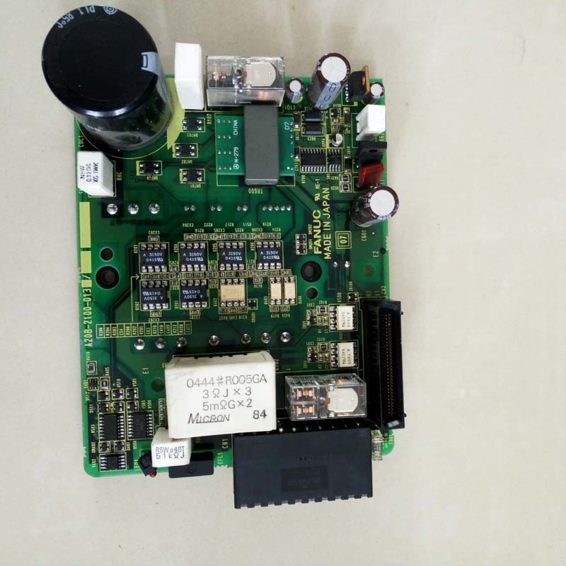
The A20B-2100-0133 is one specific board within this series, serving the drive function for which it was designed and manufactured.
Key Product Information
| Parameter |
Value |
| Part Number |
A20B-2100-0133 |
| Series |
A20B-2100 |
| Manufacturer |
FANUC Corporation |
| Type |
Drive PCB |
| Application |
FANUC CNC drive systems |
Drive PCBs — The Working Layer Between Logic and Power
In a FANUC servo or spindle amplifier module, the PCB stack performs distinct functions at different layers. The A20B-2100 series occupies a critical intermediate layer:
Control boards (A20B-2101 series): Receive axis commands from the CNC, run the current control algorithm, and output gate signals. These boards handle digital signals and relatively low power.
Drive/power boards (A20B-2100 series): Interface between the control board and the high-current IGBT switching devices. These boards carry gate drive signals to the power transistors, manage current feedback signals from current sensors, implement hardware-level protection trips, and in some variants handle active power conversion functions.
The A20B-2100-0133 operates at this drive board level — translating the control board's commands into the precise gate timing that the power devices need to produce regulated motor current.
Application Scenarios
Drive module power board fault: A servo or spindle module develops an overcurrent alarm that appears immediately on enabling the drive. Current in the motor circuit at that instant confirms the control board is sending gate signals, but the output is incorrect. The A20B-2100-0133 drive board is identified as the fault. Board replacement restores correct output behaviour.
Planned drive maintenance: A facility conducting scheduled overhaul of high-hours Alpha-i drive modules replaces the A20B-2100-0133 as part of a drive PCB refresh programme, resetting the board's service life ahead of age-related failure.
FAQ
Q1: How do I determine whether the A20B-2100-0133 or the control board (A20B-2101 series) has failed?
A failed A20B-2100 drive board typically causes power output symptoms — overcurrent, asymmetric output, or hardware protection trips. A failed A20B-2101 control board typically causes communication or logic symptoms — FSSB communication errors, drive failing to reach readiness without output faults, or erratic response to commands. Fault symptoms pointing to the output stage first — especially alarms that trip under load but not during low-current testing — point toward the A20B-2100-0133.
Q2: Does replacing A20B-2100-0133 require servo parameter changes?
No. Servo and spindle parameters are held in the CNC's main parameter memory, not in the drive PCBs. Replacing the A20B-2100-0133 does not alter any CNC parameter. After fitting and powering the system, the drive should re-establish normal communication with the CNC and resume operation under the existing parameter set. Verify at low speed before returning to full production.
Q3: Is the A20B-2100-0133 compatible with specific drive module current ratings or is it used across a range?
Drive PCBs in the A20B-2100 series are often common to a range of current ratings within a module family — the power devices change with the current rating, but the control and drive board logic remains the same across the range. Confirm the specific module model from the drive nameplate and cross-reference against the spare parts list before ordering to verify the A20B-2100-0133 covers the installed module's rating.
Q4: What safety steps apply before accessing the A20B-2100-0133 inside a drive module?
The drive module's DC bus retains dangerous voltage after mains power is removed. Allow the capacitor discharge time specified in the FANUC maintenance manual for the applicable module — or confirm with a calibrated DC voltmeter that the bus is below the safe threshold — before opening the module housing. The A20B-2100-0133 operates at bus voltage levels in normal service; ensuring the bus is fully discharged is a non-negotiable safety requirement.
Q5: Can the A20B-2100-0133 be repaired rather than replaced?
Component-level repair of FANUC drive PCBs is offered by specialist service centres. For the A20B-2100 drive board family, repair is technically possible when the failure involves discrete components such as gate driver ICs, current sense resistors, or protection components. For production-critical machines where turnaround time is critical, board-for-board replacement with the A20B-2100-0133 is typically faster than repair. Both options are valid depending on the application's urgency and budget.

 Your message must be between 20-3,000 characters!