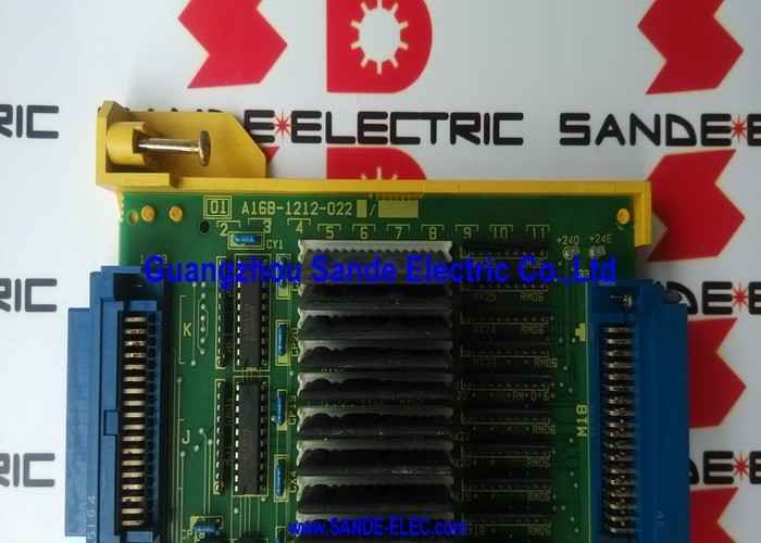
A16B-1212-0220 | FANUC Series 0-C C7 I/O Board — 104 DI / 72 DO / 0-MC / 0-TC / 0-MD / 0-TD / Non-Surface-Mount / Fully Populated
104 Inputs and 72 Outputs — Machine Control at Scale
The A16B-1212-0220's signal count reflects the needs of a fully-equipped CNC machine tool. Count the signals required on a typical machining centre:
Inputs to CNC (104 available): Axis overtravel limit switches (6–12), tool length probe, coolant level sensor, hydraulic pressure switches, door open/closed, pallet clamped, tool magazine position sensors, tool breakage detection, spindle oil level, safety mat sensor, axes brake released confirmation, cycle start/feed hold buttons, feedrate override switch stages, spindle speed override switch stages, mode selector switch contacts, auxiliary function completion signals — the list across a complex machine easily reaches 80–100+ inputs.
Outputs from CNC (72 available): Coolant pump relay, high-pressure coolant, hydraulic system start, axis brake release, door lock, spindle start direction contacts, tool magazine advance/retract, pallet clamp/unclamp, coolant ON/OFF indicator lamp, alarm indicator, cycle active lamp, spindle run indicator, feed hold indicator, programme end signal, auxiliary M-code relay outputs — 60–70 outputs on a complex machine is straightforward.
The C7's 104/72 capacity covers the full complement of a complex CNC machine tool without requiring a second I/O board.
Key Specifications
| Parameter |
Value |
| Designation |
C7 (fully populated) |
| Digital Inputs |
104 |
| Digital Outputs |
72 |
| Compatible |
0-C, 0-D, 0-F, 0-Mate-C/F |
| Machine Types |
0-MC, 0-TC, 0-TTC, 0-MD, 0-TD |
| Construction |
Non-surface-mount |
C7 — The Fully-Specified Configuration
Within the Series 0-C I/O board family, three variants exist in the A16B-1212-022x range:
| Part Number |
Designation |
DI |
DO |
| A16B-1212-0220 |
C7 |
104 |
72 |
| A16B-1212-0221 |
C6 |
80 |
56 |
| A16B-1212-0222 |
C5 |
40 |
40 |
The C7 (A16B-1212-0220) is the fully populated variant — the complete I/O board with all input and output circuits assembled. C6 and C5 are progressively reduced versions for simpler machine tools where fewer I/O points are needed.
Replacing a C7 with a C6 or C5 would result in missing I/O addresses in the PMC ladder — signals that the ladder programme expects to find would simply not exist on the smaller board, causing PMC alarms or incorrect machine behaviour. Always replace C7 with C7.
Application Scenarios
0-MC machining centre I/O fault: A FANUC 0-MC machining centre develops random PMC alarm codes. Some inputs report incorrect states despite confirmed correct field wiring. The A16B-1212-0220 board is identified through systematic fault isolation. Replacement restores correct input and output operation across all 104/72 points.
0-TC twin-turret lathe I/O configuration: A twin-turret 0-TC lathe with two turrets and associated interlocking uses the full 104/72 I/O capacity of the A16B-1212-0220 to manage all turret position switches, hydraulic circuits, and part-present sensors from a single board.
FAQ
Q1: What signals connect to the A16B-1212-0220's output terminals?
The board's digital outputs drive machine devices via relay contacts or transistor outputs. Typical connections include: cooling pump motor starters, solenoid valve coils, indicator lamp circuits, door lock solenoids, and signal outputs to auxiliary machines. Each output circuit has a maximum voltage and current rating defined in the Series 0-C hardware manual. Exceeding the output ratings causes transistor or relay failure on the board — always verify load specifications before connecting external devices.
Q2: What are the differences in applications between 0-MC and 0-TC when both use the A16B-1212-0220?
Both 0-MC (machining centre) and 0-TC (turning centre) use the same A16B-1212-0220 board, but their PMC ladder programmes use the 104/72 I/O points differently. On an 0-MC, many inputs/outputs are dedicated to tool changing, pallet handling, and spindle orientation. On an 0-TC, the same I/O addresses control chucking, tailstock, and bar feed functions. The board hardware is identical — the PMC programme determines the functional assignment.
Q3: Is the A16B-1212-0220 repairable?
Repair is viable for this board because the non-surface-mount construction makes component-level access straightforward for a qualified technician. Common failure modes — blown output transistors, failed input optocouplers, power supply component failure — are repairable at component level.
Q4: How is the address of the A16B-1212-0220's I/O points defined in the PMC?
The I/O address assignment for the A16B-1212-0220 is defined by the Series 0-C CNC's system parameter settings — specifically the I/O configuration parameters that map physical board slots to PMC I/O addresses. These parameters define which PMC address corresponds to which physical input or output terminal on the board. After fitting a replacement board, no address re-configuration is needed unless the board is fitted in a different physical slot than the original.


 Your message must be between 20-3,000 characters!