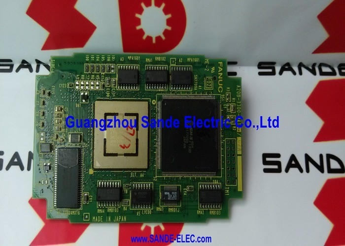
A20B-3300-0410 | FANUC 9-Inch CRT Display Control Module — Monochrome CRT Display / CNC Operator Interface / A20B-3300 Series
9-Inch CRT — The Operator's Window Into the CNC
Every interaction between a machining centre or lathe operator and the CNC's software passes through the display. The operator reads current axis positions, enters tool offset values, reviews alarm codes, edits programme lines, and navigates the CNC's menu system — all through the 9-inch screen in front of them. Without a functioning display, the operator's ability to interact with the CNC is severely compromised.
The A20B-3300-0410 is the module that drives this display. It receives display data from the CNC's main processor and converts it into the analog video signals that drive the 9-inch CRT — the horizontal and vertical deflection signals, the intensity signal (for monochrome CRT, a single brightness channel), and the sync pulses that synchronise the electron beam with the image content.
Key Product Information
| Parameter |
Value |
| Part Number |
A20B-3300-0410 |
| Display Type |
9-inch CRT (monochrome) |
| Function |
CRT display control module |
| Series |
A20B-3300 |
| Application |
FANUC CNC operator display |
How a CRT Display Control Module Works
The CNC's main processor generates display content as a stream of character and graphics data — the text, numbers, and simple graphics elements that make up the CNC's screens. This data passes to the A20B-3300-0410 display module, which performs several conversion steps:
Character rendering: The module reads character code data from the CNC and converts it into the pixel patterns required to draw recognisable alphanumeric characters on the CRT. FANUC CNC displays use a defined character set — the module's font memory holds the pixel pattern for each character.
Sync timing: The module generates the horizontal and vertical sync signals that control the CRT's electron beam raster scan. The sync timing must match the CRT monitor's deflection frequency precisely. Incorrect timing causes the image to roll, shake, or fail to appear.
Intensity modulation: As the electron beam sweeps the screen, the module modulates its intensity according to whether the current beam position should be lit or dark. This produces the white or green phosphor characters on a dark background characteristic of monochrome CNC CRT displays.
When the A20B-3300-0410 fails, the CRT goes blank or displays a corrupted, unstable image — while the CNC's machining functions continue unaffected.
Application Scenarios
CNC display failure: A FANUC CNC machining centre powers up and operates normally — axis positions update, the programme runs, and alarms clear — but the 9-inch display shows no content. The CRT monitor hardware is tested and found intact. The A20B-3300-0410 display control module is identified as the fault. Replacement restores the operator display.
Partial display corruption: The 9-inch CRT on a FANUC CNC lathe shows partial display content — some characters appear correctly but others are missing or corrupted. The fault is traced to the A20B-3300-0410 module's character generation circuitry. Replacement restores the full, clean display.
FAQ
Q1: Can the A20B-3300-0410 drive a 14-inch CRT or LCD instead of the 9-inch CRT?
No. The A20B-3300-0410 is calibrated for the deflection geometry and sync timing requirements of a 9-inch CRT. A 14-inch CRT has different deflection and timing requirements; the image geometry would be incorrect. LCD monitors require a digital or VGA-format video signal — not the analogue CRT drive signals generated by the A20B-3300-0410. For 14-inch colour CRT systems, use the appropriate 14-inch display module; for LCD replacement, an appropriate CRT-to-LCD converter or display retrofit is required.
Q2: How does a display module failure differ in appearance from a failed CRT tube?
A CRT tube failure tends to be progressive — gradual dimming, loss of focus, reduced brightness, or a bright horizontal line as the vertical deflection fails. A display module failure is typically sudden — the image disappears completely or corrupts immediately without gradual degradation. Testing by substituting a known-good display module (or a known-good CRT tube on the same signal outputs) isolates the fault to one component.
Q3: Does replacing the A20B-3300-0410 require CNC parameter adjustment?
No. The display module is a hardware component — it does not store CNC parameters or require software configuration. After fitting the replacement and powering up, the CNC loads its display content into the module and the operator display should restore immediately. No parameter changes or software configuration steps are required.
Q4: Is it possible to upgrade from the 9-inch CRT to a flat-panel LCD display?
LCD retrofit solutions for FANUC CNC systems replace the 9-inch CRT with a modern flat-panel display. Such retrofits typically use a compatible LCD panel matched to the CNC's video output signal, often combined with a video format converter. The A20B-3300-0410 module may remain in the system to generate the video signal that the LCD retrofit's converter accepts — or the retrofit may include a complete display interface replacement. Consult a qualified FANUC CNC service provider for the correct LCD retrofit approach for the specific CNC model.
Q5: What is the relationship between the A20B-3300-0410 and the CNC's graphics option?
The A20B-3300-0410 drives the standard operator display — the CNC's character-based screen for parameter entry, programme editing, and alarm display. FANUC CNC systems can optionally have a separate graphics function that generates tool path graphics displays. The graphics function may use a separate graphics module (such as a colour graphics option) in addition to the standard display module. The A20B-3300-0410 drives the standard display regardless of whether the graphics option is installed.



 Your message must be between 20-3,000 characters!