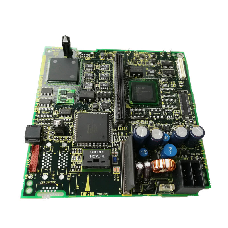
A20B-8100-0821 | FANUC Series 0i-B Digital LCD Driver PCB — 8.4-Inch / 9.5-Inch LCD/MDI Unit / F0i-B CNC Display Board
LCD Display in the 0i-B CNC — What the Driver Board Does
The FANUC Series 0i-B CNC's operator interface is a separate LCD/MDI unit — a combined display and keyboard assembly that connects to the CNC's main control unit. The LCD panel shows the operator's interface: axis positions, programme content, alarm messages, tool offsets, and all CNC screens.
Between the CNC's video signal and the physical LCD panel, the A20B-8100-0821 digital LCD driver PCB performs the critical conversion. It receives the digital display data from the CNC, converts it into the specific timing signals and voltage levels required by the LCD panel, and drives the panel's pixel array and backlight control to produce a legible, correctly formatted display image.
Without the A20B-8100-0821 functioning correctly, the LCD panel receives incorrect or no drive signals — resulting in a blank display, corrupted image, or flickering screen.
Key Specifications
| Parameter |
Value |
| CNC System |
FANUC 0i-B (F0i-B), 0i-A |
| LCD Compatibility |
8.4-inch and 9.5-inch |
| Unit Type |
Separate LCD/MDI unit |
| Board Type |
Digital LCD driver PCB |
| Series |
A20B-8100 |
8.4-Inch and 9.5-Inch — Two Display Sizes, One Board
The A20B-8100-0821 supports both 8.4-inch and 9.5-inch LCD panels within the 0i-B LCD/MDI unit range. The two sizes represent different physical LCD panel options used by machine tool builders in the 0i-B generation:
8.4-inch LCD: Compact display size used in smaller 0i-B CNC operator panels — space-efficient for turning centres and small machining centres where operator panel real estate is limited.
9.5-inch LCD: Slightly larger panel providing more readable display area — used in 0i-B systems where a larger operator panel was specified.
The driver board's timing parameters and signal levels support both screen sizes, making the A20B-8100-0821 the correct replacement for 0i-B systems with either display size. Confirm the physical panel size from the existing unit before ordering.
Application Scenarios
0i-B display failure: A FANUC 0i-B CNC lathe shows a blank display on the operator panel. The CNC continues to execute programmes normally — confirming the CNC main unit is intact. Investigation confirms the LCD panel and backlight are functional when tested with an external signal. The A20B-8100-0821 LCD driver board inside the LCD/MDI unit is identified as the fault. Replacement restores the operator display.
Display corruption on 0i-B machining centre: A 0i-B machining centre's 8.4-inch LCD shows garbled characters or a flickering image that changes with machine vibration. The A20B-8100-0821 develops an intermittent signal fault. Replacement resolves the display corruption.
FAQ
Q1: Is the A20B-8100-0821 compatible with both 0i-A and 0i-B systems?
The A20B-8100-0821 is for "0i-A, 0i-B controls." Both 0i-A and 0i-B generations used similar separate LCD/MDI unit architectures with 8.4-inch and 9.5-inch displays. Confirm the specific LCD/MDI unit's part number against the spare parts documentation for the applicable CNC before ordering.
Q2: What is the difference between a digital LCD driver PCB and an analogue LCD driver?
A digital LCD driver sends display data as discrete digital signals matched to the LCD panel's native digital interface. An analogue driver converts video data to a continuous analogue signal. Modern LCD panels use digital interfaces for better image quality and noise immunity. The A20B-8100-0821 is the digital type — appropriate for the LCD technology used in 0i-B era FANUC CNC display units.
Q3: Can a failed A20B-8100-0821 damage the LCD panel?
A driver PCB failure can produce abnormal voltage levels or timing signals at the LCD panel's input connectors. In most cases, a failed driver board causes the display to go blank or show corrupted content without permanently damaging the LCD panel itself. However, sustained incorrect voltage levels from a shorted driver component could potentially stress the LCD panel. Inspect the LCD panel visually after fitting a replacement driver board — confirm the display image is correct across the full screen before declaring the repair complete.
Q4: Does replacing the A20B-8100-0821 require any CNC parameter changes?
No. The LCD driver PCB is a hardware display interface — it does not carry CNC parameters. After fitting the replacement A20B-8100-0821 and reconnecting the LCD/MDI unit, the CNC should produce a correct display immediately on power-up without any parameter modification. If display content is misaligned or incorrectly formatted after replacement, verify that the CNC's display type parameter matches the installed LCD panel size (8.4-inch or 9.5-inch).
Q5: What is the signal cable that connects the LCD/MDI unit to the CNC main unit?
The separate LCD/MDI unit connects to the CNC's main board through a dedicated display signal cable. This cable carries digital display data (video signal in LVDS or similar digital format), power supply rails for the LCD/MDI unit, and keyboard signal returns. The cable type and connector are defined in the FANUC Series 0i-B connection manual. Cable condition should be checked when investigating display faults — a damaged or poorly connected signal cable can produce symptoms similar to a failed A20B-8100-0821 board.


 Your message must be between 20-3,000 characters!