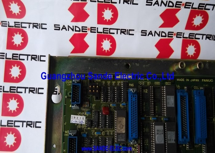
A16B-1210-0430 | FANUC Series 10/11 Dual Analog Add-On Axis Board — 2-Axis / Pulse Coder × 2 / 5th & 6th Axis / 10-M / 10-T / F11 / F110
Extending the Axis Count — What "Add Axis" Means
The FANUC Series 10 and Series 11 CNC platforms are designed for multi-axis machine tools. The base system controls a defined number of axes through its main axis boards. But some machines require more axes than the base configuration provides:
A twin-turret CNC lathe, for example, needs four axes — X1, Z1 for the first turret and X2, Z2 for the second. A 5-axis machining centre needs three linear axes plus two rotary axes. These applications exceed the two or three axes the main CNC board handles alone.
The A16B-1210-0430 is the expansion board that closes this gap. Plugging this board into the CNC adds two additional analogue axis channels to the system — extending the CNC from its base axis count to the higher number required by the machine. With the A16B-1210-0430 installed, a 4-axis machine becomes possible from a 2-axis base system, or a 5-axis and 6-axis configuration becomes reachable.
Key Specifications
| Parameter |
Value |
| Axis Channels |
2 (add-on) |
| Interface |
Analogue + pulse coder feedback |
| Feedback |
Pulse coder × 2 |
| Drive Compatibility |
M-series 6047 / 6050 DC drives |
| Compatible |
10-M, 10-T, 10-MF, 10-TF, F11M, F11T, F110 |
| Construction |
Non-surface mount PCB |
Applications — Twin Turret Lathes and 5-Axis Machining Centres
The A16B-1210-0430 most commonly appears in two machine types:
Twin-turret CNC lathes: Two tool turrets, each with its own X and Z axis. The main axis board controls the first turret (X1, Z1). The A16B-1210-0430 adds the second turret axes (X2, Z2), enabling synchronised or independent twin-turret turning in one machine pass.
5-axis machining centres: Three linear axes from the main board; the A16B-1210-0430 adds the 4th and 5th rotary axes (typically A and B or B and C). This configuration allows simultaneous 5-axis contouring for complex aerospace and die/mould components.
Application Scenarios
Twin-turret lathe axis fault: A CNC lathe with twin turrets develops an alarm on the second turret's X-axis. Inspection confirms the A16B-1210-0430 add-on axis board is the fault source. Replacing the board restores the second turret's axis operation.
5-axis machining centre 5th-axis alarm: A machining centre running a FANUC Series 10-MF control develops a persistent servo alarm on the 5th axis. After confirming the drive and motor are functional, the A16B-1210-0430 add axis board is identified as the fault. Board replacement resolves the alarm.
FAQ
Q1: Can the A16B-1210-0430 be used with Series 12 or Series 16 CNCs?
The A16B-1210-0430 is specifically designed for the analogue-era Series 10 and Series 11/110 CNC platforms. Series 12 and later FANUC digital systems use different axis board architectures and different add-axis boards. The A16B-1210-0430 is not compatible with digital axis interface CNCs.
Q2: What DC servo drives are compatible with the A16B-1210-0430?
The board interfaces with FANUC's M-series DC velocity control amplifiers — specifically the 6047 and 6050 models. These were the last-generation DC servo drives in FANUC's product range before the transition to AC servo drives. The board also works with the first generation of FANUC AC servo drives for the Series 10. Later FANUC AC digital drives (Alpha, Beta series) are not compatible with this analogue interface board.
Q3: Does removing the A16B-1210-0430 affect the main axis channels?
No. The A16B-1210-0430 is a purely additive board — it adds two axis channels to the system without affecting the main board's existing axes. Removing or replacing the A16B-1210-0430 does not interrupt the main board's 2 or 3 axis channels. Only the two add-on axes (typically 5th and 6th) are affected by this board's status.
Q4: How is the A16B-1210-0430 positioned in the CNC controller rack?
The board plugs into a defined slot in the Series 10/11 CNC controller rack — the slot designated for the additional axis module. The slot position is specified in the FANUC Series 10/11 hardware connection manual. The board edge connector interfaces with the rack's backplane; the servo drive cables connect to the board's front panel connectors for the analogue output and pulse coder feedback signals.
Q5: What CNC parameters need to be set after fitting a replacement A16B-1210-0430?
Parameters for the add-on axes — axis type (linear or rotary), direction of travel, pulse coder resolution (pulses per motor revolution), axis name assignment, and servo loop gains — must be verified after the replacement. These are held in the CNC's main parameter memory and are not changed by the board replacement itself. However, confirming the parameter settings before returning the machine to production ensures the add-on axes behave correctly with the new board installed.

 Your message must be between 20-3,000 characters!