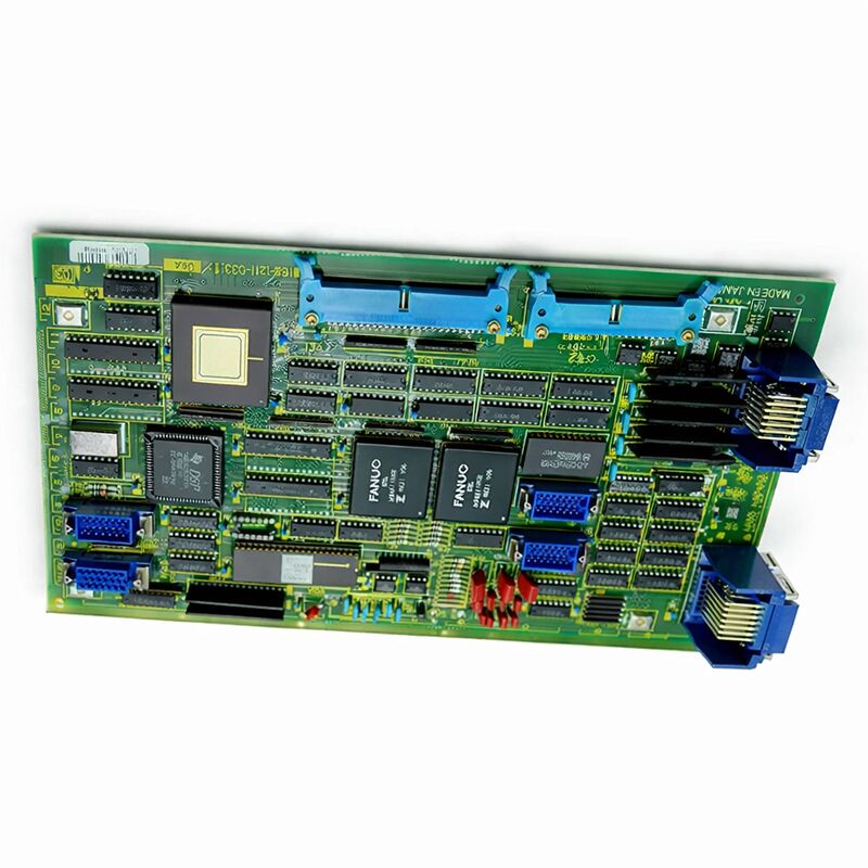
FANUC A16B-1210-0450 | Additional Axis Resolver PCB — System 11, Dual Resolver Input, Japan Origin
Part Number: A16B-1210-0450
Manufacturer: FANUC Corporation (Japan)
Product Type: Additional Axis Resolver PCB (R,R Type)
Board Series: A16B-1210
Resolver Inputs: 2 (Dual Resolver)
Compatible Systems: FANUC System 11 (11A)
Overview
The A16B-1210-0450 is the additional axis resolver PCB for FANUC System 11 CNC controls. It provides dual resolver feedback inputs — accepting position and speed signals from two resolver-type transducers connected to additional axes beyond the controller's base configuration.
The board processes these resolver signals into usable position and velocity data for the CNC's axis control algorithm.
Resolver feedback was the standard position sensing technology for FANUC axis systems in the System 11 generation. Resolvers are rugged electromechanical transducers that convert shaft angle into analog electrical signals.
They have no semiconductor components exposed to the environment and tolerate vibration, temperature variation, and contamination better than optical encoders. FANUC's System 11 era machines used resolver feedback extensively on both standard and additional axes.
The add axis board for System 11 addresses a specific machine configuration need.
The base System 11 controller handled a primary set of axes.
When a machine tool required additional axes — a fourth or fifth axis, a rotary table, an auxiliary linear axis — the A16B-1210-0450 provided the feedback interface for those additional positions. Without this board, the additional axes have no position feedback path to the CNC.
Key Specifications
| Parameter |
Value |
| Part Number |
A16B-1210-0450 |
| Manufacturer |
FANUC Corporation |
| Product Type |
Additional Axis Resolver PCB |
| Resolver Type |
R,R (Resolver / Resolver — dual input) |
| Number of Resolver Inputs |
2 |
| Board Series |
A16B-1210 |
| Compatible Systems |
FANUC System 11 (11A) |
| Design |
Plug-in PCB for main controller board |
| Origin |
Japan |
| Operating Temperature |
0 – 55°C |
| Storage Temperature |
−20 – 60°C |
| Humidity |
75% RH max (non-condensing) |
| Condition Available |
New (surplus) / Refurbished / Repaired |
Resolver Feedback — The Technology
Resolvers work on transformer principles. A primary winding on the rotor receives an excitation signal. Two secondary windings on the stator, offset 90 degrees, produce output voltages proportional to the sine and cosine of the shaft angle.
The ratio of these two outputs defines the position uniquely within one revolution. An electronic circuit — on this board — converts the analog sine and cosine signals into a digital position value.
This signal processing is the core function of the A16B-1210-0450.
The raw resolver signals arrive as analog voltages. The board's resolver-to-digital conversion circuit reads the sine/cosine amplitudes, computes the angle, tracks incremental changes to determine full position, and delivers the result to the CNC's axis control software as a position count.
Each of the two resolver inputs on this board is independent.
Axis 1's resolver connects to one input, Axis 2's resolver to the other. The board handles both simultaneously, delivering position data for both axes to the controller.
FANUC System 11 Context
FANUC System 11 was a high-capability CNC platform for its generation — designed for machining centres and complex turning centres that required more axes and more processing power than simpler controllers could provide.
The system used a modular board architecture where different functional boards — main CPU, add axis, option boards — occupied slots in the controller rack.
The A16B-1210 series covers the option and add-axis board family for this controller generation.
The -0450 is the resolver variant — for machines whose additional axes use resolver feedback.
Machines using pulse coder (encoder) feedback on additional axes use different board variants in the same series.
System 11 machines remain in service at facilities that maintain their production equipment well.
Repair parts for this controller generation are increasingly sourced from surplus and refurbished inventory rather than new production.
Fault Diagnosis — When This Board Is the Suspect
An axis fault that is isolated specifically to the additional axes — while the primary axes run normally — points toward the hardware that handles those axes specifically.
The A16B-1210-0450 covers the feedback interface for the two additional resolver axes.
If those axes show position errors, drift, or servo alarms while primary axes are unaffected, this board is among the first hardware to investigate.
Resolver cable faults and resolver-to-board connector faults produce symptoms similar to board failure. Before replacing the board, check the resolver cables for damage, confirm connector seating, and measure the resolver excitation signal at the board's resolver connectors.
If excitation is present and the resolver outputs are correct but the CNC still alarms, the board's conversion circuit may be at fault.
FAQ
Q1: The fourth axis on the System 11 machine shows a servo alarm. The first three axes are fine. Could the A16B-1210-0450 be the fault?
A servo alarm isolated to the axes served by the add axis board — with primary axes unaffected — is consistent with a fault in this board or in the resolver feedback path. First check the resolver cables and their connectors.
If the cables are intact and the resolver itself tests correctly, the board's resolver-to-digital conversion is the next suspect.
Q2: Can a resolver be tested independently of the A16B-1210-0450?
Yes. Apply the correct excitation frequency and voltage to the resolver's primary winding and measure the sine and cosine outputs. At a known shaft angle, the output amplitudes should reflect the sine and cosine of that angle.
If the resolver outputs are correct and the board still reports an error, the board is the fault. If the resolver outputs are incorrect or absent, the resolver or its cable is the fault.
Q3: Is this board directly interchangeable between different System 11 CNC units?
The A16B-1210-0450 is functionally defined by its resolver input type (dual resolver) and its compatibility with System 11 architecture.
If the replacement board carries the same part number, it is a hardware-compatible substitute.
After installation, confirm the axis parameters for the additional axes are correctly set — resolver-related parameters may need verification.
Q4: The machine uses resolver feedback on the main axes and encoders on the additional axes. Can the A16B-1210-0450 be used?
No. The A16B-1210-0450 is specifically the resolver (R,R) variant. If the additional axes use pulse coder (encoder) feedback, a different A16B-1210 variant matching the encoder interface type is required.
Check the existing board's label before sourcing a replacement.
Q5: How should this board be stored as a spare?
Store in anti-static packaging at room temperature in a dry environment. Avoid temperature extremes and humidity.
The board contains no battery and no degrading components beyond normal component aging.
Inspect the edge connector and resolver input connectors for oxidation before installation if the board has been in storage for an extended period.

 Your message must be between 20-3,000 characters!