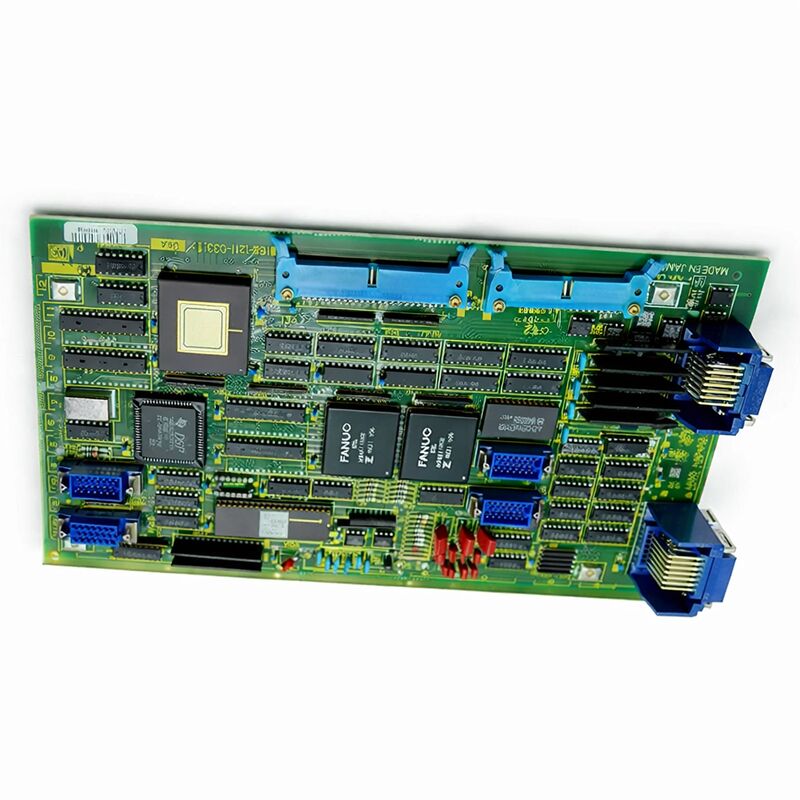
FANUC A16B-1211-0272 | System 10 / 11 Two-Channel Digital Add-Axis PCB — 6057 Series Drive Interface, Japan Origin
Part Number: A16B-1211-0272
Manufacturer: FANUC Corporation (Japan)
Product Type: 2-Channel Digital Additional Axis Control PCB
Board Series: A16B-1211
Compatible Systems: FANUC System 11, 11A, 11M, 11T, 11F — and System 10
Axis Channels: 2 (peripheral dual-axis controller)
Compatible Drives: 6057 series digital AC servo amplifiers (also 6058 series)
Encoder Input: Pulse coder square signal
Construction: Through-hole (non-surface-mount)
Status: Discontinued by Manufacturer
Overview
The A16B-1211-0272 is the two-channel digital axis controller board for FANUC's System 10 and 11 CNC platforms. It is a peripheral axis card — not a standalone controller — that adds two digitally controlled servo axes to a System 10/11 installation.
Working alongside the main controller board and other axis cards in the system, it provides the digital servo interface for its two assigned axes, connecting the controller's interpolated position commands to the 6057 or 6058 series digital AC servo drive units that drive the motor.
System 10 and 11 were FANUC's high-capability CNC platforms of their generation. Machining centres, turning centres, and complex production machines equipped with these controllers demanded multi-axis coordinated motion — some requiring four, five, or more simultaneous controlled axes.
The peripheral axis card architecture supported this by letting machine builders and systems integrators combine multiple axis cards around the main controller, each card handling its assigned group of axes.
The A16B-1211-0272, with its two-channel capacity, was central to this expansion scheme.
The board carries the GE FANUC designation alongside the FANUC markings, reflecting the joint venture era during which many of these controllers were marketed. Non-surface-mount construction gives the board a robustness that has proved out over decades in machine tool service.
The through-hole components are individually accessible for inspection and, where applicable, replacement.
Key Specifications
| Parameter |
Value |
| Part Number |
A16B-1211-0272 |
| Manufacturer |
FANUC Corporation |
| Product Type |
2-Channel Digital Additional Axis PCB |
| Board Series |
A16B-1211 |
| Compatible Systems |
FANUC System 10, 11, 11A, 11M, 11T, 11F |
| Axis Channels |
2 |
| Compatible Drives |
6057, 6058 series digital AC servo |
| Encoder Interface |
Pulse coder (square signal) |
| Construction |
Through-hole (non-SMT) |
| Origin |
Japan |
| Operating Temperature |
0 – 55°C |
| Status |
Discontinued by Manufacturer |
| Condition Available |
New (surplus) / Refurbished / Repaired / Exchange |
Peripheral Axis Card Architecture in System 10/11
FANUC's System 10 and 11 were designed around a distributed axis control model.
The main controller board managed the overall CNC processing burden — program interpretation, interpolation calculations, PMC execution, and operator interface handling.
The axis cards managed the servo interfaces. Each axis card took its position commands from the controller, computed the corresponding velocity demand, and delivered it to the servo drive for that axis.
The A16B-1211-0272 handled two axes simultaneously. In a four-axis machining centre, for example, two A16B-1211-0272 boards could serve all four axes — one board for the X and Y axes, another for the Z and a fourth axis.
In a five-axis machine, the two boards plus a single-channel card completed the set. The controller coordinated all boards in real time, so all axes could move simultaneously in precise, interpolated trajectories.
The board's dual-channel design reflects the practical architecture of its era: two axes per board was the balance point between board complexity and system modularity.
Single-channel boards served machines where individual axes had different configurations; dual-channel boards served the common case where pairs of axes could share a board.
Drive Interface: 6057 and 6058 Series Compatibility
The 6057 series digital AC servo amplifiers were the primary drive units paired with System 11 in FANUC's product line at the time.
These drives received digital velocity commands from the axis card and converted them to the motor current needed to achieve the commanded velocity.
The feedback path — position data from the motor's pulse coder — returned through the axis card to the controller.
The pulse coder feedback is a square wave signal.
The board's input circuitry processes these square waves, counting the pulses to determine axis position. The precision of the position count determines the controller's resolution of position measurement.
The interface was designed for the pulse coder types used with the 6057/6058 series motors of the period.
The A16B-1211-0272 was also designed to run with a range of spindle and servo interfaces, accommodating both digital and serial drive types, and in some configurations, analogue interfaces.
This flexibility made it adaptable to the variety of machine designs that incorporated System 10/11 controls.
Legacy Support and Serviceability
System 10/11 machines, though old by any contemporary standard, remain in productive operation at shops that invested in them and maintain them. The mechanical quality of these machines is often excellent.
The electronics are the component with the practical service life limit — and among the electronics, the axis cards are among the most likely to need attention, given the direct role they play in servo control.
Through-hole construction is a serviceability advantage at this age. Aged electrolytic capacitors — the most common age-related failure mode in PCBs of this vintage — can be replaced using standard soldering equipment.
A board that exhibits erratic axis behaviour, intermittent servo alarms, or other symptoms consistent with degraded power supply filtering can often be restored by a preventive capacitor replacement, extending its useful service life considerably.
FAQ
Q1: Both axes served by the A16B-1211-0272 alarm simultaneously at power-on. The drives and motors show no independent faults. Is this board the cause?
Simultaneous dual-axis alarms at power-on, with confirmed good drives and motors, is the characteristic pattern of an axis card failing to complete its initialisation.
Both axes share the board's common circuitry for power supply and controller communication.
A failure in these shared circuits affects both axes equally. Inspect and reseat the board's connectors first. If reseating doesn't resolve the alarms, the board's power supply or interface circuitry requires repair or replacement.
Q2: Only one of the two axes on this board alarms, while the other is normal. Does this mean the board's single-channel circuit has failed, or could the cause be external?
Single-axis alarms with one channel normal and one channel faulty are more likely to have external causes than a board-level single-channel failure. The drive unit, motor, or encoder cable for the affected axis are the first items to check.
Board single-channel faults do occur, but connector and drive faults are considerably more common.
Verify the drive, motor, and encoder feedback connection for the faulty axis before concluding the board is at fault.
Q3: The machine runs normally at low speeds but produces excessive following errors during rapid traverse on both axes served by this board. Other axes are unaffected. What could cause this?
Following errors on rapid traverse that don't appear at low speed suggest the velocity command signal from the board is not reaching the drive units cleanly at higher demand levels. This can be caused by degraded signal conditioning components — capacitors or resistors — in the board's velocity output circuits.
It can also indicate connector contact resistance that is insignificant at low frequencies but causes signal attenuation at the higher update rates needed during rapid traverse.
Q4: A replacement A16B-1211-0272 was obtained but carries a different hardware revision suffix. Is it safe to install?
Minor hardware revision changes within the same base part number typically represent component or layout improvements that maintain backward compatibility. Later revision boards installed in place of earlier revisions are generally compatible.
However, confirming compatibility against the machine's documentation or with a qualified FANUC service resource before installation is the responsible approach, particularly for high-value production machines where downtime from an incompatible installation would be costly.
Q5: The machine builder is no longer in business. How can the correct axis assignment parameters be determined for the replacement board?
FANUC's System 10/11 hardware manuals, which describe the axis card configuration and parameter assignments, are separate from the machine builder's documentation and are available through FANUC's documentation network and specialist industrial documentation suppliers.
These manuals describe the parameter settings that assign each axis card's channels to specific axis numbers in the controller.
With the controller's parameter backup (if available) and the hardware manual, the correct configuration can be established.

 Your message must be between 20-3,000 characters!