FANUC A16B-1211-0273 | System 11 Single-Channel Digital Axis PCB — Servo Control for 6057 Drives, Japan Origin
Part Number: A16B-1211-0273
Manufacturer: FANUC Corporation (Japan)
Product Type: Single-Channel Digital Axis Control PCB
Board Series: A16B-1211
Compatible Systems: FANUC System 11, 11A, 11M, 11T, 11MF, 11TF
Axis Count: 1 (single-channel peripheral axis controller)
Compatible Drives: 6057 series digital AC servo amplifiers
Construction: Through-hole (non-surface-mount)
Overview
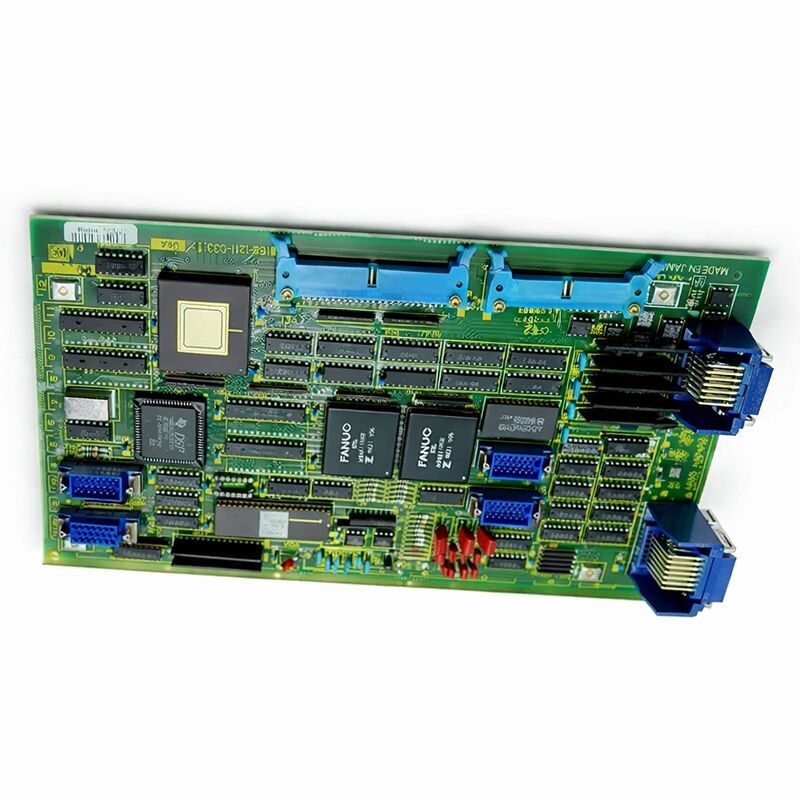
The A16B-1211-0273 is the single-channel digital axis control board for FANUC's System 11 CNC — the peripheral axis card that manages one servo axis in a System 11 installation.
It functions as the primary servo interface for a single axis, generating the digital commands that drive the connected 6057 series servo amplifier unit and processing the position feedback returned from the motor's encoder.
In the System 11's distributed axis control architecture, each axis board serves its assigned axis independently, with all boards coordinating through the main controller to produce the simultaneous multi-axis motion a machining or turning operation requires.
The System 11 was one of FANUC's flagship CNC platforms before the transition to the 0-C and Series 15 generation. It was deployed in machining centres, turning centres, and multi-function machine tools across a wide range of industries.
The axis boards that controlled those machines were the A16B-1211-0273 and its siblings — boards designed for the later, more capable digital implementations of the System 11. When FANUC released the 0-C and 15-series controllers, the System 11 was superseded, but the machines it controlled continued operating and continue to operate today.
The board is non-surface-mount — through-hole construction, with component leads inserted through the PCB and soldered on the reverse.
This is the construction technology of its era, and it has a practical advantage for a board that is now decades old: components are individually accessible for inspection and replacement.
Key Specifications
| Parameter |
Value |
| Part Number |
A16B-1211-0273 |
| Manufacturer |
FANUC Corporation |
| Product Type |
Single-Channel Digital Axis Control PCB |
| Board Series |
A16B-1211 |
| Compatible Systems |
FANUC System 11, 11A, 11M, 11T, 11MF, 11TF |
| Axis Channels |
1 |
| Compatible Drive |
6057 series digital AC servo amplifiers |
| Construction |
Through-hole (non-SMT) |
| Interface |
Digital servo (6057 series) |
| Origin |
Japan |
| Operating Temperature |
0 – 55°C |
| Storage Temperature |
−20 – 60°C |
| Condition Available |
New (surplus) / Refurbished / Repaired |
System 11 Axis Architecture
FANUC's System 11 used a modular peripheral axis card approach. The main controller board handled the overall CNC processing — program interpretation, interpolation mathematics, PMC execution, operator interface.
The axis cards interfaced with the servo drives, one card per axis, and were distributed around the controller's bus.
Each card received its position command from the main controller and processed the encoder feedback for its axis.
The A16B-1211-0273 was fitted to the later, more powerful System 11 digital configurations — specifically those interfacing the 6057 series digital AC servo drive units.
The 6057 is a digital drive that communicates through the same type of digital signal interface the axis board generates.
This pairing was the state-of-the-art servo implementation for the System 11 platform at the time, offering improved servo performance over earlier analogue-interfaced configurations.
The board was standard across the 11, 11A, 11M (machining centre), 11T (turning centre), 11MF, and 11TF variants of the System 11.
These different designations reflect the application and configuration differences of the controller, not fundamental hardware changes.
The axis card's function — controlling one servo axis through its 6057 drive — was the same regardless of which System 11 variant the machine used.
Interface with the 6057 Drive
The 6057 series servo amplifier units were FANUC's digital servo drives for the System 11 generation.
The A16B-1211-0273 provides the control interface that these drives require — the digital servo command signal that conveys the velocity demand from the controller to the drive, and the path for the encoder position feedback to return to the controller.
The 6057 drive takes this command, executes its current control loop, and delivers the appropriate motor current to the connected servo motor.
The drive's function is power conversion and current regulation; the intelligence is in the axis card.
The axis card computes the velocity demand from the controller's position error calculation, and the 6057 executes it.
This clean separation of function means that when a fault occurs, understanding which side of the interface it is on determines the replacement component.
Fault codes and alarm patterns guide this diagnosis. A fault code indicating a position error — the axis is not following its commanded position — with no drive alarm suggests the axis card's position command or feedback processing has degraded.
A drive alarm indicating overcurrent suggests the motor or drive is the fault location.
Through-Hole PCB — Maintenance Advantages
Decades in service have demonstrated the durability of well-designed through-hole PCBs. The A16B-1211-0273 is old enough that its electrolytic capacitors are approaching or past their designed service life under normal operating conditions.
Capacitors age as their electrolyte slowly evaporates, and their capacitance drops while their equivalent series resistance (ESR) rises. On an axis control board, degraded power supply capacitors allow voltage ripple that manifests as erratic servo behaviour — position errors, unexplained velocity fluctuations, or alarms that appear and clear without clear mechanical cause.
Through-hole capacitors can be replaced with basic soldering equipment and appropriate replacements.
This is a practical refurbishment for a board that is otherwise functional.
A competent electronics technician can replace the electrolytic capacitors on the A16B-1211-0273 in a few hours, restoring the board's power supply performance and potentially extending its service life by many more years.
FAQ
Q1: The System 11 machine produces a servo alarm on one specific axis at power-on. Other axes initialise normally. The 6057 drive for that axis shows no independent alarm. Is this the A16B-1211-0273?
A single-axis servo alarm at power-on with the drive reporting no independent fault and other axes normal is consistent with the axis card failing to complete its initialisation sequence. The axis card must establish communication with its drive during power-on.
If the card's communication circuit has failed, the drive receives no commands, the controller reports a servo fault, but the drive itself — which is functioning electrically — shows no alarm of its own.
Inspect the connector between the axis card and the drive unit, then proceed to board replacement if the connector is confirmed good.
Q2: The axis controlled by the A16B-1211-0273 runs at slightly incorrect speed during DNC cutting cycles. The position readout is accurate but the cutting quality has degraded. No alarms are generated. What could be happening?
Speed inaccuracies during cutting without position alarms suggest the velocity control loop has a disturbance.
The axis card generates the velocity demand signal; if the signal-conditioning circuits on the card have degraded components — aged resistors, leaking capacitors — the velocity command may have slight errors that produce incorrect cutting speeds without generating position following errors.
Compare the servo diagnostic data for this axis against a reference baseline from when the machine performed correctly.
Q3: A16B-1211-0273 boards from two different System 11 machines appear to have different hardware revision labels. Are they interchangeable?
The A16B-1211-0273 with different hardware revision suffixes (e.g., /01A, /02A) typically represents PCB layout or component changes made during production while maintaining the same functional specification.
In most cases, later revision boards are backward compatible with earlier revision sockets and configurations.
However, this should be verified against the System 11 hardware documentation for the specific machine configuration before swapping revisions.
Q4: A replacement A16B-1211-0273 has been obtained. What checks should be performed before installation?
Before installing the replacement, inspect the connector contacts for damage or oxidation. For a surplus board that may have been in storage, check for any capacitor damage — bulging, leakage residue — that would indicate storage condition problems.
Verify the board's revision suffix is compatible with the installation.
After installation, the axis should be jogged slowly through its range before running automatic cycles, and the position feedback should be verified against the machine's known travel limits.
Q5: This board is discontinued by FANUC. Are repair services still available?
Yes. The System 11 axis board supply chain remains active through the industrial automation service market.
Component-level repair services — where the specific failed component is identified and replaced — are available from CNC service specialists who routinely work on this generation of FANUC hardware. The through-hole construction makes component-level repair practical.
Exchange services, where a tested refurbished board is provided in exchange for the faulty original, are also available and provide the fastest restoration option when production cannot wait for a repair.

 Your message must be between 20-3,000 characters!