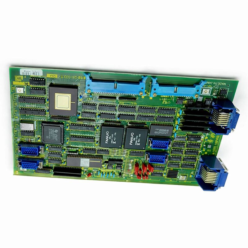
FANUC A16B-1211-0331 | Series 0-B Additional Single Axis Control PCB — 5th/6th Axis Expansion, Japan Origin
Part Number: A16B-1211-0331
Manufacturer: FANUC Corporation (Japan)
Product Type: Additional Axis Control PCB (Single Channel)
Board Series: A16B-1211
Compatible Systems: FANUC Series 0-B (0-MB, 0-TTB, 0-P4B, 0-PB)
Axis Count: 1 (additional axis expansion)
Interface: Digital — controls S-series (6058) digital servo drives
Construction: Through-hole (non-surface-mount)
Overview
The A16B-1211-0331 is the additional single-axis control board for FANUC's Series 0-B CNC controllers. It expands the axis control capability of 0-B configurations — the 0-MB machining centre, 0-TTB twin-turret turning centre, 0-P4B palletiser, and 0-PB boring machine variants — by adding one more digitally controlled servo axis to the existing axis complement.
Series 0-B was the last and most capable generation of FANUC's 16-bit CNC architecture. It was the evolution that followed the 0-A series, bringing improved processing power and enhanced capabilities while maintaining the reliable, field-proven design philosophy that made the 0-series commercially successful.
The 0-MB configuration supported machining centres with up to four axes in its standard form.
The A16B-1211-0331 added the fifth or sixth axis when the machine's design required more than the base configuration provided.
The board mounts on the 0-B controller's main board alongside the A16B-1211-0320 Sub CPU command board, which coordinates the additional axis operation.
This pairing — command board plus axis board — was the standard approach for axis expansion in the 0-B platform.
The axis board handles the servo interface for the additional axis: the PWM digital commands to the 6058 series drive and the encoder feedback processing from the motor.
Key Specifications
| Parameter |
Value |
| Part Number |
A16B-1211-0331 |
| Manufacturer |
FANUC Corporation |
| Product Type |
Additional Single Axis Control PCB |
| Board Series |
A16B-1211 |
| Compatible Systems |
FANUC Series 0-MB, 0-TTB, 0-P4B, 0-PB |
| Additional Axis |
1 (5th or 6th axis) |
| Drive Interface |
Digital (controls 6058 series drives) |
| Required Companion |
A16B-1211-0320 Sub CPU command board |
| Construction |
Through-hole (non-SMT) |
| Origin |
Japan |
| Operating Temperature |
0 – 55°C |
| Storage Temperature |
−20 – 60°C |
| Condition Available |
New (surplus) / Refurbished / Repaired |
The 0-B Platform and Axis Expansion
The FANUC 0-B series represented the mature state of the 16-bit CNC era. The base axis count handled the needs of most machine configurations, but many machine designs — particularly machining centres with rotary tables, twin-pallet machines, and multi-function turning centres — required one or two more axes than the standard board set provided.
FANUC's solution was the additional axis board architecture.
Rather than requiring a completely different controller for machines with more axes, the expansion could be achieved by adding the specific axis board to the existing controller configuration.
The A16B-1211-0331 provided one such additional axis. When two additional axes were needed, two boards were used.
The axis board generates the digital PWM servo commands for the additional axis's drive unit.
The drive unit for this axis is the same 6058 series digital servo amplifier used for the primary axes.
The axis board also receives the encoder position feedback from the additional axis motor, completing the closed-loop position control for that axis.
The controller sees the additional axis as another axis in its configuration.
The CNC's program uses it with the same G-code axis commands as any other axis.
The addition is transparent to the part program — the expanded axis behaves identically to the primary axes from the operator's and programmer's perspective.
Through-Hole Design and Practical Serviceability
Like other boards from the 0-B era, the A16B-1211-0331 uses through-hole construction. Components are mounted by inserting their leads through the PCB and soldering on the reverse. This is a fundamentally different approach from the surface-mount construction that became standard in later FANUC generations.
Through-hole construction has practical advantages for a board that is now decades old.
Components are individually accessible and replaceable with standard soldering equipment.
A capacitor that has aged into failure can be identified and replaced without SMT rework tools. Connector contacts can be cleaned and tested individually.
For boards of this vintage, the most common aging failure mode is electrolytic capacitor degradation. Capacitors dry out slowly over time, and their impedance increases as their electrolyte evaporates.
On an axis control board, degraded capacitors in the power supply section produce unstable supply voltages that cause erratic axis behaviour or intermittent alarms.
Preventive capacitor replacement on a board showing age-related symptoms is often the most effective restoration approach.
Companion Board Requirement
The A16B-1211-0331 does not operate as a standalone addition. It requires the A16B-1211-0320 Sub CPU command board to be present and functional.
The Sub CPU board provides the processing logic that coordinates the additional axis operation and interfaces with the main controller's bus.
The axis board handles the servo interface for the axis the Sub CPU commands.
When diagnosing an additional axis fault on a 0-B machine, both the Sub CPU board and the axis board are potential fault locations.
A fault in the Sub CPU board typically affects all additional axes coordinated by that board. A fault in the axis board typically affects only the specific axis that board serves.
This distinction guides the diagnostic and replacement decision.
FAQ
Q1: The 5th axis on a 0-MB machining centre produces a servo alarm at power-on. The primary axes (1–4) initialise normally. The 5th axis motor and drive appear undamaged. Is the A16B-1211-0331 likely at fault?
An additional axis alarm with normal primary axis operation is consistent with either the axis board or the Sub CPU command board having failed. The primary axes use different board hardware, so a fault in the additional axis board set doesn't affect them.
Check the Sub CPU board first — its failure affects all additional axes simultaneously. If only the 5th axis alarms, the A16B-1211-0331 is more likely the fault.
Confirm the drive and motor are undamaged, then proceed to board diagnosis.
Q2: Both the 5th and 6th axes (both served by additional axis boards) alarm at power-on simultaneously. What does this indicate?
Simultaneous failure of multiple additional axes points to the Sub CPU command board rather than individual axis boards. Both axis boards depend on the Sub CPU for their operational commands.
A failed Sub CPU causes both axes to alarm regardless of the axis boards' condition.
Inspect the Sub CPU board, verify its connectors, and if the board's condition is suspect, replace the Sub CPU board before the axis boards.
Q3: The 0-B machine has been running reliably for many years and recently the 5th axis started showing intermittent position errors that appear and clear without consistent triggering. The axis board and the 5th axis drive test as functional. What else could cause this?
Intermittent position errors that don't follow a clear pattern on an otherwise reliable machine often point to an aging connector or a degraded electrolytic capacitor on one of the boards in the additional axis chain.
The connector between the axis board and the Sub CPU board, or the connectors to the drive unit, can develop high-resistance contacts over time.
Clean and reseat all connectors in the 5th axis signal path. If this doesn't resolve the intermittent fault, capacitor replacement on the axis board is the next step.
Q4: A replacement A16B-1211-0331 was obtained. After installation, the 5th axis shows a different alarm from the original. What should be checked?
A different alarm after board replacement usually indicates a configuration or connector issue rather than a faulty replacement board.
Verify that all connectors are correctly and fully seated on the new board — the connector to the Sub CPU board and the connector to the drive unit both need to be fully engaged.
Also confirm that the axis assignment parameters in the CNC are configured correctly for the 5th axis.
A parameter mismatch can produce alarms that appear hardware-related.
Q5: Can the A16B-1211-0331 operate in any 0-series controller, or is it limited to the 0-B?
The A16B-1211-0331 was specifically designed for the FANUC 0-B series controller platform. The board's interface, bus protocol, and connector configuration match the 0-B architecture.
It is not interchangeable with additional axis boards from other 0-series generations (0-A, 0-C, or 0-D), even if those boards serve a similar functional purpose.
The 0-A and 0-C generations used different board specifications for axis expansion. Always confirm the board's series compatibility before installation.

 Your message must be between 20-3,000 characters!