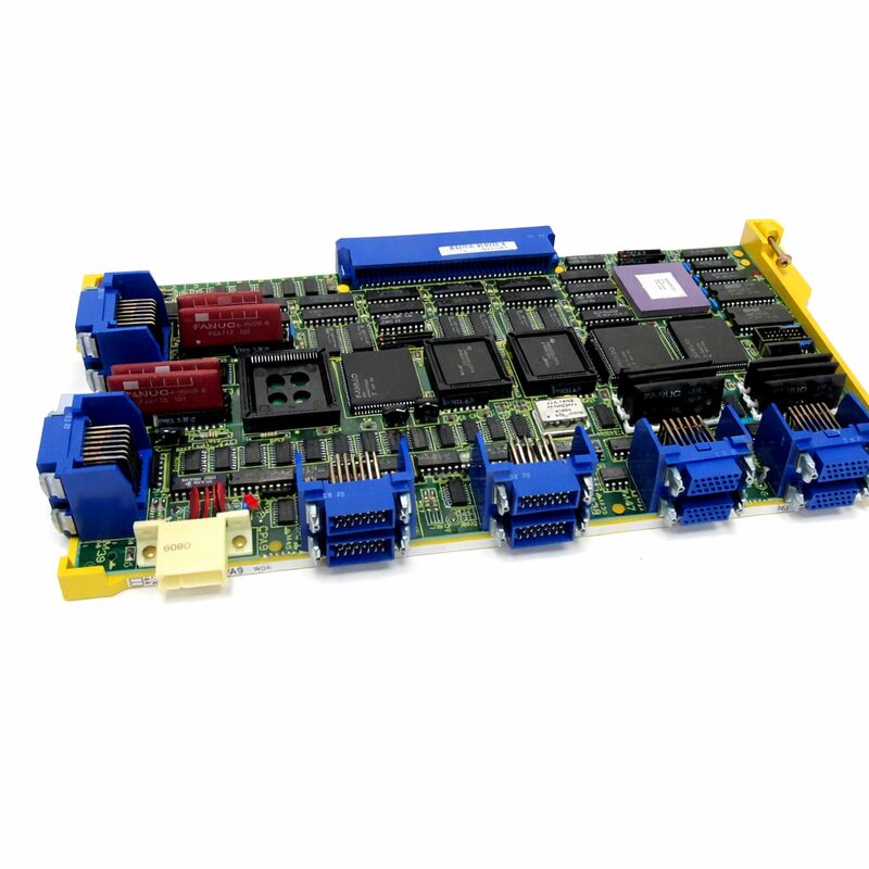
FANUC A16B-2200-0091 | 3-Channel Axis Control Board — Series 15-MA / 15-TA CNC, Japan Origin
Part Number: A16B-2200-0091
Manufacturer: FANUC Corporation (Japan)
Product Type: 3-Channel Axis Control PCB
Board Series: A16B-2200
Compatible Systems: FANUC Series 15-MA, 15-TA (Series 15 Model A)
Compatible Drives: 6058 and 6066 series digital AC servo amplifiers
Axis Channels: 3
Overview
The A16B-2200-0091 is a 3-channel axis control board for FANUC's Series 15 Model A CNC controllers — the high-performance multi-axis platform used in complex machining centres, large turning centres, and multi-path machine tools of the era.
This board is responsible for the servo communication and PWM signal generation that drives three servo axes through the digital AC servo amplifier units they connect to.
The Series 15 was FANUC's flagship CNC at the time of its introduction.
It was designed for high-axis-count applications where multiple simultaneous controlled axes, multi-path configurations, and high-accuracy positioning were the primary requirements.
The controllers for these machines — large, multi-board assemblies with modular axis cards, system boards, graphics units, and PMC boards — required axis control boards of exactly this type to manage each group of servo axes. The A16B-2200-0091 handled three of them.
The board uses conventional through-hole construction rather than the surface-mount design that became standard in later FANUC generations.
This is characteristic of the Series 15 Model A era — the boards are physically larger and the components are through-hole mounted, which makes component-level diagnosis and repair more accessible than with later SMD designs.
The connectors are robust and the layout is practical for field service in large machine installations.
Key Specifications
| Parameter |
Value |
| Part Number |
A16B-2200-0091 |
| Manufacturer |
FANUC Corporation |
| Product Type |
3-Channel Axis Control PCB |
| Board Series |
A16B-2200 |
| Compatible Systems |
FANUC Series 15-MA, 15-TA (Model A) |
| Compatible Drives |
6058 and 6066 series digital AC servo amplifiers |
| Axis Channels |
3 |
| Construction |
Through-hole (non-surface-mount) |
| Signal Type |
PWM digital servo control |
| Origin |
Japan |
| Operating Temperature |
0 – 55°C |
| Storage Temperature |
−20 – 60°C |
| Humidity |
75% RH max (non-condensing) |
| Condition Available |
New (surplus) / Refurbished / Repaired |
Axis Control in Series 15 Architecture
The Series 15 controller architecture distributed axis control across dedicated axis control boards. The main system board provided the CNC's processing core — program interpolation, PMC execution, operator interface management.
The axis control boards provided the servo interface — the real-time PWM signal generation and encoder feedback processing that created the closed-loop position control for each group of servo axes.
The A16B-2200-0091 generates the PWM (pulse-width modulation) digital commands that the connected servo amplifiers — the 6058 and 6066 series drives — translate into motor current.
The PWM signal encodes the velocity command: its duty cycle determines how much current the drive delivers to the motor.
The board simultaneously processes the position feedback from the encoder on each axis motor, comparing commanded position to actual position and continuously adjusting the velocity command to close the position error.
This separation of the CNC's interpolation function from the servo control function was architecturally deliberate.
The CNC interpolator calculates target positions.
The axis control board executes them.
Both operate at high speed but with different timing constraints — the interpolator works in millimeter coordinates at machining speeds, while the servo board works in encoder counts at kHz servo update rates.
Multi-Card Configurations
A major Series 15 machine could require multiple axis control cards. The 3-channel design of the A16B-2200-0091 meant that a 9-axis machine needed three such boards. A 12-axis machine needed four.
The Series 15 architecture supported this by allowing axis cards to be twinned or combined into multi-card configurations where the main system board coordinated all of them.
The board connects back to the system through defined interface connections.
The addresses for the three axes it serves — BASE 0, 1, or 2 in the board's signal reference system — determine which three axes in the overall machine axis numbering this board handles.
Getting this assignment correct after a board replacement is essential: an incorrectly assigned axis control board would drive the wrong axes or produce communication conflicts within the controller.
Through-Hole Construction and Repairability
The A16B-2200-0091's through-hole construction is a maintenance advantage. On a surface-mount board, damaged components require SMT rework equipment and skills that are not universally available.
On a through-hole board, a damaged resistor, capacitor, or IC can be removed and replaced with standard soldering equipment and appropriate replacement components.
For a board of this age and with the through-hole accessibility, component-level repair is often the first option to pursue when the board fails.
Series 15 controller boards that fail due to aged electrolytic capacitors — a common aging failure mode — can often be restored by replacing the affected capacitors with new ones, which is a manageable repair for a qualified PCB technician.
FAQ
Q1: One of the three axes controlled by the A16B-2200-0091 shows a persistent servo alarm at power-on, while the other two axes on this board are normal. Is the board faulty?
A single-axis alarm with two normal axes on the same board suggests the board is partially functional. The board's circuitry for the affected axis channel has failed while the other two channels remain good.
This is consistent with a component failure in the specific channel's circuitry rather than a board-level power or communication failure. Confirm the servo amplifier and motor on the affected axis are undamaged before concluding the board's channel is at fault.
If external components test good, board repair or replacement is appropriate.
Q2: All three axes on the A16B-2200-0091 generate alarms simultaneously. The other axis boards in the machine are operating normally. What does this indicate?
Simultaneous failure of all three channels on a single board, while other axis boards remain operational, points to a board-level fault in the shared circuitry — the power supply section, the main communication interface to the system board, or a common signal bus on the A16B-2200-0091 itself.
Check the board's power supply connector and the communication cable connector before concluding the board has a PCB fault.
If connectors are confirmed good, the board requires repair or replacement.
Q3: The board was removed and reseated as part of a general maintenance inspection. After reinstallation, one axis that was previously normal now generates an alarm. What happened?
An axis that fails after a board reseating typically indicates a connector issue created during the reinsertion — a bent contact pin, a connector that is not fully engaged, or a cable that was not reconnected correctly.
Remove the board again, inspect the connector pins carefully, reconnect all cables, and reseat the board with deliberate, full engagement.
In most cases this resolves a post-maintenance alarm.
Q4: Are there other Series 15 axis control boards that can substitute for the A16B-2200-0091 if this exact part is unavailable?
The A16B-2200 series axis control boards for Series 15 include several variants for different axis counts and configurations. Whether another variant is a functional substitute depends on the specific board's channel count, interface type, and axis addressing scheme matching the requirements of the machine configuration.
Substitution across Series 15 axis board variants is sometimes possible but must be verified against the machine's configuration documentation and the system board's expectations. Do not assume physical compatibility implies functional compatibility.
Q5: The machine has been idle for several years. After restoration to service, the axis boards including the A16B-2200-0091 produce intermittent alarms. What should be investigated?
Extended idle time affects electrolytic capacitors throughout the controller. These capacitors dry out slowly during storage, and their capacitance and ESR (equivalent series resistance) degrade.
When the controller powers up after a long idle period, degraded capacitors cause erratic supply voltages that produce intermittent and inconsistent alarms.
A preventive capacitor replacement on the axis boards — replacing all electrolytic capacitors with new ones — is the recommended refurbishment procedure before returning a long-idle machine to production service.

 Your message must be between 20-3,000 characters!