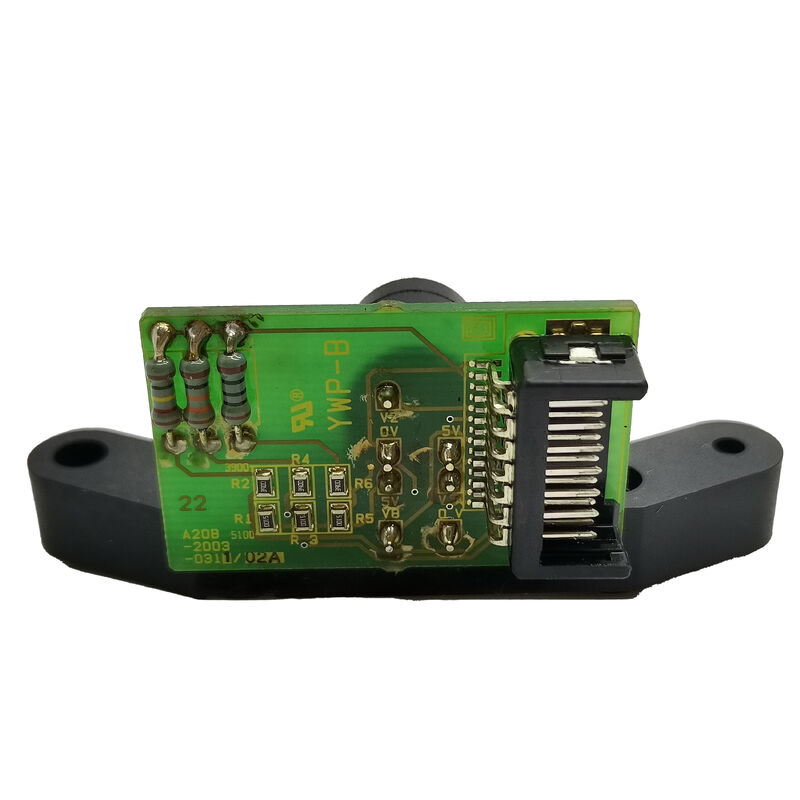
FANUC A20B-2003-0311 | MZi Sensor Signal Processing PCB — Part of A860-2110-V001 Alpha i Spindle Sensor Assembly
Part Number (PCB): A20B-2003-0311
Complete Assembly: A860-2110-V001 (MZi spindle sensor unit — ordered and supplied as one)
Manufacturer: FANUC Corporation (Japan)
One Part Number, One Complete Unit
The A20B-2003-0311 is the signal processing PCB inside the FANUC A860-2110-V001 MZi spindle sensor assembly. It is not available separately. Whether the request is for A20B-2003-0311 or A860-2110-V001, the result is the same complete sensor unit — because the PCB and sensor housing are always supplied together and the PCB's alignment within the housing is factory-set.
Attempting to disassemble the sensor to replace only the PCB risks disturbing the magnetic pickup alignment, which cannot be re-set in the field. The correct service path is always the complete A860-2110-V001 unit.
What the MZi Sensor Does — and Why It Matters
Alpha i spindle motors use a different feedback approach than servo motors. Servo axes use optical pulse coders (the A860-2xxx absolute pulsecoder family). Spindle motors use magnetic sensors — the MZi type detects the passage of teeth or poles on a target ring on the spindle shaft. The A20B-2003-0311 PCB conditions the raw magnetic pickup signal into clean digital pulses the spindle amplifier can process.
Three spindle functions depend on this sensor providing accurate, uninterrupted feedback:
Speed regulation. The amplifier reads MZi feedback continuously to hold commanded spindle speed under varying cutting loads. Degraded signal causes speed hunting — visible in cut quality and audible in machining sound — before it triggers an alarm.
Rigid tapping. Spindle rotation and Z-axis feed must stay synchronised in real time during every tapping cycle. A single missed pulse from the MZi sensor can strip a thread or break a tap. Tap breakage on otherwise correctly specified tooling is one of the clearest early indicators of a degrading sensor.
Spindle orientation. The tool changer requires the spindle to stop at a precise angular position to engage the drive key. The MZi sensor provides the position reference. A failed sensor produces SP0742 (orientation failure) or similar alarms and stops tool changes entirely.
Key Specifications
| Parameter |
Value |
| PCB Part Number |
A20B-2003-0311 |
| Sensor Assembly |
A860-2110-V001 |
| Sensor Type |
MZi magnetic pickup |
| Connection |
12-pin |
| Cable |
Not included |
| Functions |
Speed feedback, rigid tapping, orientation |
| Status |
Discontinued — aftermarket available |
FAQ
Q1: Can the A20B-2003-0311 PCB be replaced independently?
No. The PCB is not sold separately and its alignment inside the sensor housing is factory-set. Any request for A20B-2003-0311 or A860-2110-V001 results in the complete sensor unit. Always replace the complete A860-2110-V001 assembly.
Q2: What are the early symptoms of a failing sensor?
Early degradation shows subtle signs before alarms appear: rigid tapping threads at the tolerance limit rather than clearly in spec, minor spindle speed variation under heavy cuts, or orientation that takes slightly longer than usual to complete. As the sensor continues to degrade, CNC alarms follow — SP0740 (speed feedback error), SP0742 (orientation failure), or SP0001 (spindle overload from inability to regulate speed). A clean alarm history pointing only to sensor-type alarms on a single spindle is a clear diagnostic signal.
Q3: Does replacing the sensor require any parameter adjustment?
After fitting a replacement A860-2110-V001, the spindle orientation position may need to be re-set. The angular relationship between the sensor and the motor shaft reference position may differ slightly on the new unit. Verify tool change alignment after replacement and adjust the spindle orientation shift parameter (SP1004 or equivalent on i-series controls) in small increments if necessary.
Q4: Is the A860-2110-V001 compatible with all alpha i spindle motors?
No. The A860-2110-V001 is specific to a defined set of alpha i spindle motor models. Other MZi sensor variants — such as the A860-2100-V001 with its A20B-2003-0310 PCB — serve different motor frame sizes. The mechanical mounting interface and target ring diameter are motor-specific. Always confirm the sensor part number against the specific spindle motor model before ordering.
Q5: The sensor is discontinued — is it still available?
Yes, through the FANUC aftermarket — specialist CNC parts companies and FANUC service network hold exchange and surplus stock. The A860-2110-V001 is one of the more commonly traded alpha i spindle components given the large installed base of machines that use it. Request a functional test confirmation before accepting any exchange unit.

 Your message must be between 20-3,000 characters!