Siemens A5E36717797 | SINAMICS S120 IGD2/R4 Power Block Board — 480V / 650VDC / 310A
Part Number: A5E36717797
Manufacturer: Siemens AG (Germany)
Product Type: IGD2/R4 Power Block Gate Drive Board (Spare Part — TIM type)
Product Family: SINAMICS S120
Overview
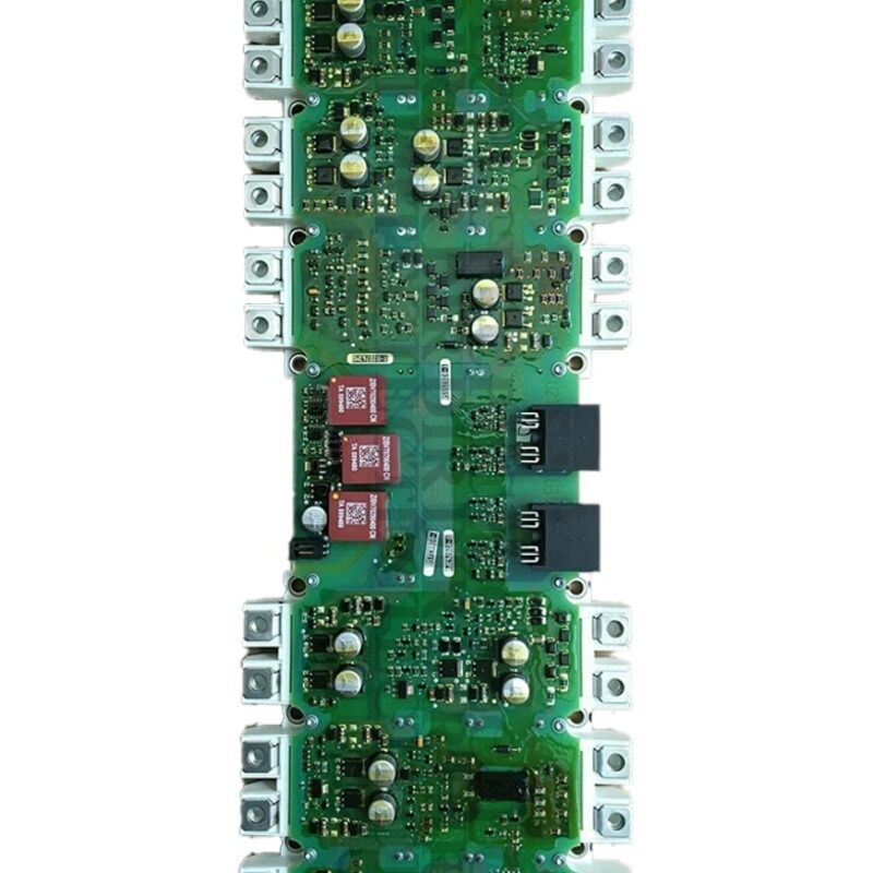
The A5E36717797 is a Siemens SINAMICS S120 IGD2/R4 power block gate drive board — the second-generation IGBT gate drive and power interface PCB for SINAMICS S120 chassis Motor Module assemblies rated at 310A and designed for 480V AC supply (650V DC bus).
This board sits within the S120 Motor Module's power block assembly, directly interfacing with the IGBT module.
It generates and delivers the gate drive pulses that switch the IGBT transistors, processes the current feedback from the shunt sensing circuits in the power block, and implements the hardware-level protection logic that shuts down the IGBTs in the event of over-current, over-voltage, or IGBT saturation faults.
The SINAMICS S120 is Siemens' high-performance modular drive platform for multi-axis and single-axis servo and vector control.
In the chassis format, the Motor Module houses the IGBT inverter stage that converts DC bus power into the variable-frequency, variable-voltage AC supply needed to drive the motor.
The motor's dynamic performance — speed accuracy, torque response, and positioning precision — depends directly on the quality of the gate drive signals generated by this board. Incorrect switching timing increases losses and reduces motor control precision.
The designation IGD2/R4 identifies this as the second-generation IGD (Inverter Gate Driver) board in the R4 form factor.
The TIM designation indicates the thermal interface material assembly type, confirming the assembly configuration within the S120 power block.
At 310A, this board serves Motor Modules in the 160kW range on a 400V system — drives found in large machine tools, extruder lines, paper machines, and heavy process applications.
Key Specifications
| Parameter |
Value |
| Part Number |
A5E36717797 |
| Manufacturer |
Siemens AG |
| Product Type |
IGD2/R4 Power Block Gate Drive Board |
| Product Family |
SINAMICS S120 |
| Supply Voltage |
480V AC |
| DC Bus Voltage |
650V DC |
| Rated Current |
310A |
| Board Type |
TIM (Thermal Interface Material assembly) |
| Country of Origin |
Germany |
IGD2/R4 — Second-Generation Gate Drive Architecture
The IGD designation identifies the IGBT gate drive function within Siemens' S120 power block architecture. The first-generation IGD boards (IGD1) served lower-current power blocks.
The second generation — IGD2 — introduced design improvements that reflect advances in IGBT technology and gate drive requirements at higher current levels.
A gate drive board operates at the boundary between low-voltage control signals and high-voltage power switching.
The Control Unit generates a digital PWM switching pattern — a sequence of on/off commands at several kilohertz — for each of the six IGBTs in the three-phase inverter bridge. The A5E36717797 receives these commands and translates them into the gate drive pulses that actually switch the IGBTs.
This translation is not trivial. An IGBT gate requires a specific charge to turn on — the gate drive must source this charge quickly enough to achieve the desired switching speed without causing excessive voltage overshoot. On turn-off, the gate drive must remove the gate charge at a controlled rate — too fast, and the collector-emitter voltage spikes dangerously; too slow, and switching losses increase.
The IGD2/R4 board's gate drive circuitry is specifically optimised for the 310A IGBT module it interfaces, balancing these competing requirements for the actual device characteristics.
Current Sensing and Protection
Beyond gate drive, the A5E36717797 handles the motor phase current measurement. Current sensors in the power block produce analogue signals proportional to the instantaneous motor current in each phase.
The board processes these signals, performing the ADC conversion and transmitting the digital current values to the Control Unit. This feedback is the heart of the CNC current control loop — the controller uses it to compute the vector control's torque-producing current component.
The board also implements hardware-level IGBT protection.
When an IGBT turns on and the voltage across it (VCE) does not collapse to near zero — indicating a short-circuit or overload condition — the board detects this within microseconds and asserts a hardware shutdown.
This desaturation protection responds faster than any software can, cutting the gate signals before the IGBT fails. At 310A, the energy stored in an uncontrolled fault current event is substantial.
The A5E36717797's protection circuits are a safety-critical function.
TIM Assembly and Installation
The TIM designation in the A5E36717797's description refers to the thermal interface material assembly type used in this power block variant. The IGBT module generates significant heat during operation — at 310A, the thermal load on the heatsink and the thermal interface between the IGBT module and the heatsink is substantial.
The TIM assembly ensures that the thermal interface between the IGD board assembly and the IGBT module maintains consistent thermal contact.
When replacing the A5E36717797, thermal interface material must be applied correctly according to Siemens' service instructions for this power block type.
Incorrect TIM application affects the thermal resistance at the IGBT-to-heatsink interface and can lead to premature thermal failures even with a correctly functioning board.
Safety precautions for this work are the same as for any S120 chassis drive service: full AC mains isolation, minimum five-minute DC bus discharge waiting period, confirmation of DC bus below 50V before access, and ESD handling for the gate drive board.
FAQ
Q1: The S120 chassis Motor Module at 310A shows a repeated F30001 overcurrent fault at partial load. The motor and cables are confirmed healthy. Could the A5E36717797 be the cause?
F30001 at partial load with a healthy motor and cables suggests either a current sensing offset drift on the IGD2/R4 board, or an IGBT gate drive imbalance creating unequal current sharing between parallel IGBT devices (if fitted).
A current sensing fault produces artificially high measured current that triggers the trip before actual current reaches the limit. Inspect the board's current sense connectors and try resetting the fault with no motor load — if F30001 persists at zero current, the current sensing section of the A5E36717797 has failed.
Q2: After replacing the A5E36717797 board, the S120 Motor Module shows an F30015 (phase failure) alarm at startup. What should be checked?
F30015 after an IGD board replacement typically indicates that one of the gate drive connectors between the new IGD2/R4 board and the IGBT module has not been fully seated. The gate drive output for one phase is missing or intermittent, producing an unbalanced output that the controller detects as a phase failure.
Power down, discharge the DC bus, and recheck every connector between the A5E36717797 and the IGBT gate terminals.
Also verify the current sense connector seating.
Q3: What is the functional difference between the A5E36717797 (310A) and the nearby part A5E36717799 (380A)? Can the 380A board replace the 310A application?
These are different boards matched to different IGBT module specifications. The 310A and 380A boards differ in gate drive parameters — gate resistance values, gate voltage levels, and desaturation threshold settings — that are optimised for the different IGBT devices used in each current rating. Installing a 380A gate drive board in a 310A power block would produce incorrect switching behaviour, increased switching losses, and potentially incorrect protection thresholds.
Only the A5E36717797 should be used in the 310A Motor Module.
Q4: The A5E36717797 is described as a TIM type. What does this mean for installation compared to non-TIM power block variants?
The TIM (Thermal Interface Material) designation indicates that the thermal interface between the IGD board assembly and the IGBT module uses a specific thermal compound or pad configuration.
During installation, the old thermal material must be completely removed from the IGBT module surface and the new board must be mated with fresh thermal interface material applied per Siemens' service procedure.
Insufficient or incorrectly applied TIM increases the thermal resistance between the IGBT and heatsink, which can cause premature over-temperature faults under load even with a correctly functioning board.
Q5: The S120 chassis Motor Module at 310A has suffered a repeated IGBT failure. After the IGBT is replaced, should the A5E36717797 also be replaced?
Yes. IGBT failures — particularly those caused by over-current or IGBT desaturation faults — expose the gate drive board to the same electrical stress event that damaged the IGBT.
The desaturation protection circuit on the A5E36717797 may have detected the fault and shut down correctly, but the transient energy during a fault event can damage components on the gate drive board that do not cause an immediate visible failure.
Replacing both the IGBT module and the A5E36717797 gate drive board simultaneously is the correct practice — it ensures that the new IGBT is not subjected to potentially compromised gate drive waveforms from a damaged board.

 Your message must be between 20-3,000 characters!