Siemens A5E02822120 | TDB Rectifier Trigger Board — 480V AC/DC Thyristor Drive Board for Converter Module
Part Number: A5E02822120
Manufacturer: Siemens AG (Germany)
Product Type: TDB — Thyristor Drive Board / Rectifier Trigger Board (assembled PCB)
Product Family: SINAMICS G120 / S120 converter and chassis drive series
Overview
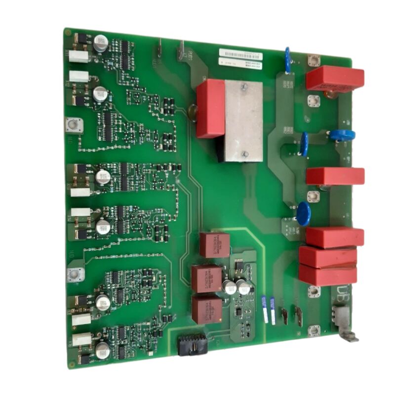
The A5E02822120 is the TDB (Thyristor Drive Board / Trigger Drive Board) — the rectifier trigger board for Siemens SINAMICS G120 and S120 converter module assemblies. Its function is the generation and distribution of gate firing pulses for the thyristor (SCR) devices in the drive's rectifier input stage.
At this level of the SINAMICS drive architecture, the converter module rectifies the incoming 480V AC three-phase supply into the DC bus voltage that feeds the inverter section. The A5E02822120 is the control PCB that tells each thyristor in that rectifier bridge exactly when to switch.
The "TDB" designation appears on the board's own label and in its Siemens documentation — it stands for Thyristor Drive Board, identifying the board's core purpose within the drive's power conversion architecture.
The TDB is distinct from the IGBT gate driver boards (IGD series) that control the inverter output section: the IGD boards handle the fast PWM switching of the motor current, while the TDB handles the slower, phase-synchronised thyristor switching of the rectifier input.
The A5E02822120 is part of a board family that also includes A5E02822121 and its sub-variants.
These boards serve different converter module configurations within the SINAMICS range, covering the higher power chassis drive applications from approximately 90 kW to 250 kW where the drive's input rectifier uses thyristors for controlled rectification.
Key Specifications
| Parameter |
Value |
| Part Number |
A5E02822120 |
| Manufacturer |
Siemens AG |
| Product Type |
TDB — Thyristor Drive Board / Rectifier Trigger PCB |
| Function |
Thyristor (SCR) firing, phase-angle control |
| Voltage |
480V AC / DC |
| Weight |
~550 g |
| Flame Rating |
UL 94V-0 (MV27) |
| Application |
SINAMICS G120 / S120 converter modules, 90–250 kW |
| Related Parts |
A5E02822121, A5E02822104-001, A5E01105817 |
| Production Status |
Discontinued |
| Country of Origin |
Germany |
TDB Function — Thyristor Rectifier Control
The SINAMICS G120 and S120 chassis drives in the higher power range use a thyristor (SCR) controlled rectifier in the input converter section, rather than a simple uncontrolled diode bridge.
This controlled rectifier gives the drive the ability to regulate the DC bus voltage build-up during pre-charge, to implement soft-start of the DC bus capacitors without inrush current damage, and in some configurations, to enable regenerative feedback of braking energy back into the AC supply.
The A5E02822120 TDB generates the gate firing pulses for the thyristors in this rectifier bridge.
It continuously monitors the three-phase AC supply voltage to detect zero crossings — the phase reference from which firing angles are calculated.
It then generates gate pulses at the commanded firing angle for each thyristor position in the six-pulse bridge. The firing angle determines how much of each AC half-cycle is converted to DC: a small firing angle (near the zero crossing) produces near-maximum DC output; a large firing angle produces reduced DC output.
During normal operation, the TDB holds the firing angle at the value that maintains the DC bus voltage within the SINAMICS drive's operating window.
During pre-charge, the firing angle is progressively reduced from maximum toward minimum to ramp up the DC bus voltage at a controlled rate.
During a regenerative braking event (in drives with regenerative rectifiers), the firing angle moves into the inversion region, allowing DC bus energy to flow back as AC into the supply.
TDB Board in the SINAMICS Drive Architecture
The SINAMICS G120 and S120 chassis drive architecture separates the control electronics into several boards: the main Control Unit (CU320 or similar), the Power Module control board, and the TDB for converter-equipped units. The A5E02822120 sits between the AC supply terminals and the DC bus, operating under commands from the higher-level control board.
The board's weight (~550 g) reflects a substantial PCB with power-handling components — pulse transformers for galvanic isolation of the thyristor gate pulses, the zero-crossing detection network for all three supply phases, gate driver ICs, and the regulatory electronics that generate firing angle commands from the DC bus voltage feedback signal.
The MV27 / UL 94V-0 substrate rating confirms that the board's PCB material meets the highest standard in UL's vertical burn classification.
In a drive cabinet where high-current thyristors, DC bus capacitors, and cooling fans share an enclosed space, a non-flame-propagating PCB substrate is an important passive safety property.
Related Board Variants
The A5E02822120 is the base variant of its board family. Related parts appearing in SINAMICS service documentation include:
A5E02822121 — a closely related TDB variant for different converter module configurations or revised production states.
The A5E02822121A and B suffixes designate further production revisions of this base design.
A5E02822104-001 — a sub-assembly or variant board associated with the same TDB family; some service documentation cross-references it to the same drive applications.
A5E01105817 — the SINAMICS V50 SCR firing card, which serves a similar thyristor trigger function in the V50 platform's rectifier section, distinct from the SINAMICS G120/S120 TDB family.
Confirming the correct variant for a specific drive requires cross-checking the installed board's exact A5E number against the drive's internal hardware documentation.
FAQ
Q1: The SINAMICS G120 chassis drive shows a DC bus undervoltage alarm immediately at startup. The AC supply voltage at the drive's input terminals has been confirmed normal. Could the A5E02822120 be the cause?
DC bus undervoltage with confirmed AC supply points directly to the TDB. If the TDB is not generating correct thyristor firing pulses, the SCR bridge does not rectify the AC supply and the DC bus fails to charge.
Alternatively, the TDB's phase synchronisation circuit may have lost lock to the supply frequency, generating firing pulses at incorrect timing and producing very low rectified DC output.
Before concluding the board has failed, verify the connections from the supply voltage sensing circuit to the TDB are intact — damaged sensing connections produce the same symptom.
Q2: The A5E02822120 board has a MV27 / UL 94V-0 rating on its PCB substrate. What does this mean in practice for industrial drive maintenance teams?
UL 94V-0 is the highest classification in UL's vertical flame burn test series. A substrate rated V-0 self-extinguishes within 10 seconds of each test flame application, with no burning drips.
In practical terms for a drive cabinet, this means the PCB will not sustain a fire or propagate combustion to adjacent components in the event of a localised component failure that generates heat.
This does not make the board fireproof, but it significantly reduces the risk of a component failure cascading into a cabinet fire. For maintenance teams, it is a certification that confirms the board meets industrial fire safety standards.
Q3: The A5E02822120 is discontinued. Can the A5E02822121 (or its A/B revision) be used as a direct replacement?
The A5E02822121 and its revision variants are closely related to the A5E02822120 in the same TDB board family and serve overlapping drive applications. In many cases they are cross-referenced as functional equivalents.
However, before installing A5E02822121 in a drive originally fitted with A5E02822120, confirm that the drive's service documentation or spare parts list accepts this substitution — minor differences in connector pinout or firmware compatibility between the two variants can occasionally affect specific drive production states.
Q4: The SINAMICS drive shows unbalanced three-phase input currents at partial load. The input supply has been confirmed balanced. Is the A5E02822120 TDB likely at fault?
Unbalanced input currents with a balanced supply is consistent with non-uniform thyristor firing angles across the six SCR positions — one or more TDB firing channels delivering pulses at a different phase angle than the others.
This asymmetry can result from a drifted timing component in the TDB's firing network, or from a damaged phase-synchronisation circuit for one supply phase.
Measure the gate pulse timing of each thyristor gate signal with an oscilloscope and compare firing angles across the three phases. Irregular angles confirm a TDB fault.
Q5: Is it possible to repair the A5E02822120 at component level rather than replacing the whole board?
Component-level repair is viable when the fault is localised to identifiable and replaceable components. On the A5E02822120, the most failure-prone components are: pulse transformers (which can develop inter-winding short circuits under sustained thermal stress), optocouplers and gate driver ICs in the firing circuit, and passive components in the zero-crossing detection network.
A specialist drive repair company with SINAMICS TDB experience can often identify the failed component from the fault symptoms and replace it, restoring the board to full function. When the fault is a damaged PCB trace or a failed IC for which no component-level replacement exists, full board replacement is required.

 Your message must be between 20-3,000 characters!