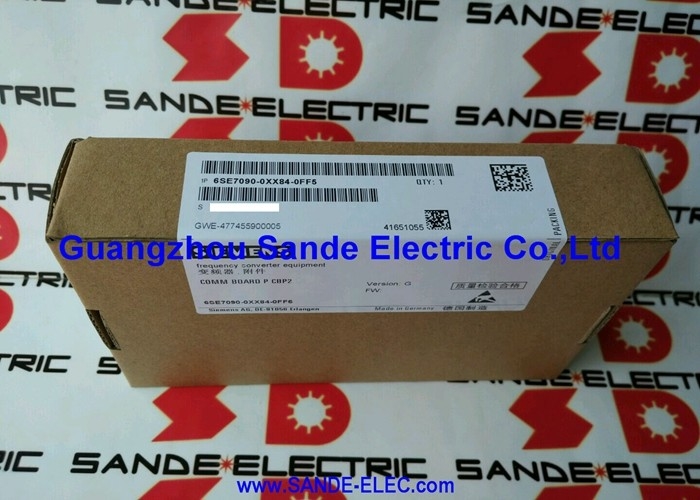
6SE7090-0XX84-0BJ0 | Siemens SIMOVERT MASTERDRIVES CUSA AFE Control Module — Active Front End Infeed / Backfeed / Firmware V2.XX
AFE Infeed — What Makes It Different
The 6SE7090-0XX84-0BJ0 is the control module for the AFE (Active Front End) infeed/backfeed unit within the SIMOVERT MASTERDRIVES system. Standard MASTERDRIVES drives use a passive diode bridge rectifier at the input — simple and reliable, but incapable of returning energy to the supply grid. The AFE unit replaces this passive front end with an actively switched IGBT bridge controlled by the CUSA module.
The AFE topology brings three major engineering advantages over a standard passive rectifier front end:
Energy regeneration (backfeed): When a drive decelerates a large mass — a press, centrifuge, hoist, or high-inertia machine — the motor operates as a generator. With a standard drive, this regenerated energy charges the DC bus until the brake resistor dissipates it as heat. With the AFE, the CUSA module controls the active front end to feed this energy back to the supply grid rather than wasting it. In continuous-cycle high-inertia applications, regenerative recovery significantly reduces energy consumption.
Active power factor correction: The AFE's active switching produces a nearly sinusoidal input current waveform — approaching unity power factor. A standard diode bridge draws peaked, distorted current with significant harmonic content. The AFE's clean sinusoidal draw reduces reactive power demand, avoids harmonic penalties, and simplifies the site's power factor correction requirements.
Stable DC bus: The CUSA module actively regulates the DC bus voltage against supply voltage fluctuations — maintaining stable motor performance even with imperfect supply quality, which is typical in industrial environments with large switching loads on the same supply.
Key Specifications
| Parameter |
Value |
| Series |
SIMOVERT MASTERDRIVES |
| Module Type |
CUSA — AFE Control Module |
| Application |
AFE-Infeed / AFE-Backfeed Unit |
| Firmware |
Version V2.XX |
| Part Format |
Universal module (6SE7090-0XX84 = fits across MASTERDRIVES variants) |
CUSA — Control Unit Servo / Asynchronous / AFE
The CUSA (Control Unit — AFE variant) is the intelligent control board that manages the AFE unit's active switching:
PWM switching control: The CUSA calculates the required switching pattern for the AFE's IGBT bridge — generating the gate drive commands that produce a sinusoidal input current waveform with controllable power factor.
DC bus regulation: The CUSA continuously monitors the DC bus voltage and adjusts the AFE switching to maintain the setpoint — absorbing supply voltage transients before they reach the drive inverters fed from the bus.
Grid synchronisation: The AFE must be synchronised to the supply frequency and phase before it can connect. The CUSA handles phase-locked synchronisation with the supply voltage, enabling smooth connection and disconnection.
Drive bus communication: The CUSA communicates with the MASTERDRIVES inverter units connected to the common DC bus — coordinating regenerative operation so that braking energy from any drive on the bus is channelled through the AFE to the grid.
Application Scenarios
AFE control module fault: A SIMOVERT MASTERDRIVES AFE infeed unit develops control-level faults — active rectification stops functioning correctly, DC bus voltage becomes unstable, or regenerative braking is lost. The 6SE7090-0XX84-0BJ0 CUSA module is identified as the fault. Replacement restores active front end function including regenerative energy recovery.
AFE firmware update: A facility upgrading MASTERDRIVES AFE units to firmware V2.XX functionality replaces the CUSA control module to introduce the updated firmware version — improving AFE performance or compatibility with newer MASTERDRIVES control units.
FAQ
Q1: What is the practical energy saving from a MASTERDRIVES AFE unit controlled by 6SE7090-0XX84-0BJ0?
The energy saving depends entirely on the application's regenerative duty cycle — how often the driven load decelerates and how much energy is returned. In continuous-cycle applications with high-inertia loads (large presses, centrifuges, hoists, test bench drives), regenerative recovery can account for 20–40% of total energy consumption. In applications with infrequent deceleration, the saving is minimal. The AFE's power factor improvement delivers additional value in sites with reactive power penalties.
Q2: What alarms indicate a fault in the 6SE7090-0XX84-0BJ0 CUSA module versus the AFE power stage?
The SIMOVERT MASTERDRIVES displays fault and alarm codes on the operator panel. CUSA control module faults typically produce: loss of AFE synchronisation alarms, DC bus regulation failures, or internal CUSA hardware faults — all pointing to the control electronics rather than the power switching stage. Power stage faults (IGBT failures, overcurrent) produce hardware overcurrent or short-circuit alarms. Distinguish the two before ordering a replacement module.
Q3: Can 6SE7090-0XX84-0BJ0 be used in any SIMOVERT MASTERDRIVES AFE unit regardless of power rating?
The 6SE7090-0XX84 module format is designed as a universal spare across the MASTERDRIVES range — the "XX" in the part number confirms cross-range compatibility. However, confirm from the specific AFE unit's documentation that 6SE7090-0XX84-0BJ0 is the correct CUSA module variant for that unit's hardware generation. Different MASTERDRIVES product generations may use different CUSA variants.
Q4: What happens to the DC bus and connected drives if 6SE7090-0XX84-0BJ0 fails?
If the CUSA module fails, the AFE unit ceases to actively control the DC bus. The system's response depends on how the MASTERDRIVES installation is configured: the drives may fault on DC bus over/undervoltage, or the installation may switch to a fallback passive rectifier if one is installed. Regenerative braking is lost — the system must dissipate braking energy through brake resistors or refuse to accept regenerative loads until the AFE is restored.
Q5: What installation precautions apply when fitting the 6SE7090-0XX84-0BJ0 replacement module?
Isolate and lock out the mains supply to the complete MASTERDRIVES system before accessing the AFE unit. The DC bus of the MASTERDRIVES system retains lethal voltage after mains isolation — follow the full capacitor discharge waiting procedure and verify DC bus voltage is below 50V before access. Handle the CUSA module with anti-static precautions. After fitting the replacement, allow the AFE to complete its synchronisation and self-test sequence before enabling connected drive inverters.


 Your message must be between 20-3,000 characters!