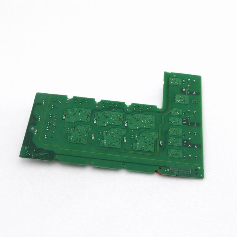
Siemens A5E00825001 | MICROMASTER 440 / 430 IGD1/R3 IGBT Drive Board — 210A / 400V / FS300R12KE3-S1 / 90–132 kW
One Assembly, Complete Power Section Restoration
The A5E00825001 is a complete repair assembly — not just the gate driver board alone. The IGD1 gate driver board and the FS300R12KE3-S1 IGBT power module are supplied together, providing everything needed to restore the MM440/MM430 inverter power section in a single replacement operation. The IGD1 board mounts directly on the IGBT module; the combined assembly bolts onto the drive's aluminium heatsink.
This assembly was manufactured at Siemens' Gerätewerk Erlangen facility — the GWE prefix in its internal reference confirms this origin. GWE-designated assemblies represent Siemens' own production rather than third-party procurement, reflecting tightly matched gate driver and IGBT characteristics.
The 210A continuous current rating operates the FS300R12KE3-S1 (300A peak capability) at a deliberate derating. The MM440/MM430 thermal budget — heatsink area, cooling airflow, ambient envelope — sets the practical sustained current limit below the IGBT's absolute peak, while also providing margin for the MM440's 150% overload capability up to 60 seconds without driving the IGBT into thermal stress.
A5E00825001 vs A5E00825002
Both assemblies serve the MM440/MM430 at high power, but they are not interchangeable:
| Part Number |
Current |
Application |
| A5E00825001 |
210 A |
MM440/MM430 90–132 kW |
| A5E00825002 |
260 A |
MM440/MM430 higher-power models |
The specific assembly is determined by the drive's order number — the power section physically accommodates only one of the two form factors. Confirm the installed assembly's A5E part number from its own label before ordering.
Key Specifications
| Parameter |
Value |
| Part Number |
A5E00825001 |
| Gate Driver |
IGD1 (R3 form factor) |
| Rated Current |
210 A |
| Rated Voltage |
400V AC / 650V DC bus |
| Included IGBT |
FS300R12KE3-S1 (300A/1200V) |
| Drive Application |
MM440/MM430, 90–132 kW |
| Dimensions |
~410 × 220 × 60 mm |
| Status |
Discontinued April 2016 |
| Origin |
Germany (GWE Erlangen) |
FAQ
Q1: The MM440 shows F0022 at power-up before any run command. Is the A5E00825001 the cause?
F0022 (fibre-optic communication fault) at power-up before a run command indicates a break in communication between the control board and the IGD1 gate driver board. First inspect all fibre-optic cables between the A5E00825001 and the control board, including connectors at both ends — a cracked or contaminated fibre is the most common cause. If fibres are confirmed good and F0022 persists, the IGD1 circuit has failed.
Q2: Does the replacement require any drive parameter recalibration?
No. The A5E00825001 stores no drive parameters — those are on the control board. After board replacement, the drive boots normally and reads its parameter set without any recalibration step. Before resuming production load, verify fibre-optic connections are correctly seated and perform a brief no-load run to confirm correct output phase currents.
Q3: After replacing the A5E00825001, the drive shows F0004 (overtemperature) at full load within minutes. What is the cause?
F0004 shortly after a power block replacement is almost certainly incorrect or missing thermal interface material (TIM) between the IGBT module base plate and the heatsink. Without correct TIM, the IGBT junction reaches overtemperature under load even while the heatsink feels only moderately warm. Remove the assembly, clean both surfaces, and re-apply TIM per Siemens' installation procedure.
Q4: How is it confirmed whether the IGBT module itself has failed or only the gate driver?
Measure collector-emitter resistance across each IGBT switch with the assembly de-energised and DC bus discharged. A healthy IGBT shows high resistance in both directions. A short-circuit reading across any switch confirms IGBT module failure — the complete assembly must be replaced. If all switches test good, the failure is in the IGD1 gate driver circuitry and component-level repair is viable.
Q5: Is there a SINAMICS equivalent for a site upgrading from MM440 to SINAMICS G120?
In the G120 platform, the equivalent power function is provided by the G120 Power Module (PM240, PM250, or PM260 depending on the application) — replaced as a complete unit rather than as a board-level assembly. For migration from 90–132 kW MM440 to SINAMICS G120, the PM240-2 or PM250-2 at the appropriate power rating provides equivalent motor control with current SINAMICS firmware and hardware support.


 Your message must be between 20-3,000 characters!