Siemens A5E00825002 | IGD1/R3-BGR Drive Board with IGBT Output Modules — 480V / 650V DC / 260A
Part Number: A5E00825002
Manufacturer: Siemens AG (Germany)
Product Type: Drive Board — IGD1/R3-BGR IGBT Gate Driver with Output Modules
Product Family: MICROMASTER 440 / MICROMASTER 430 (MM440 / MM430)
Overview
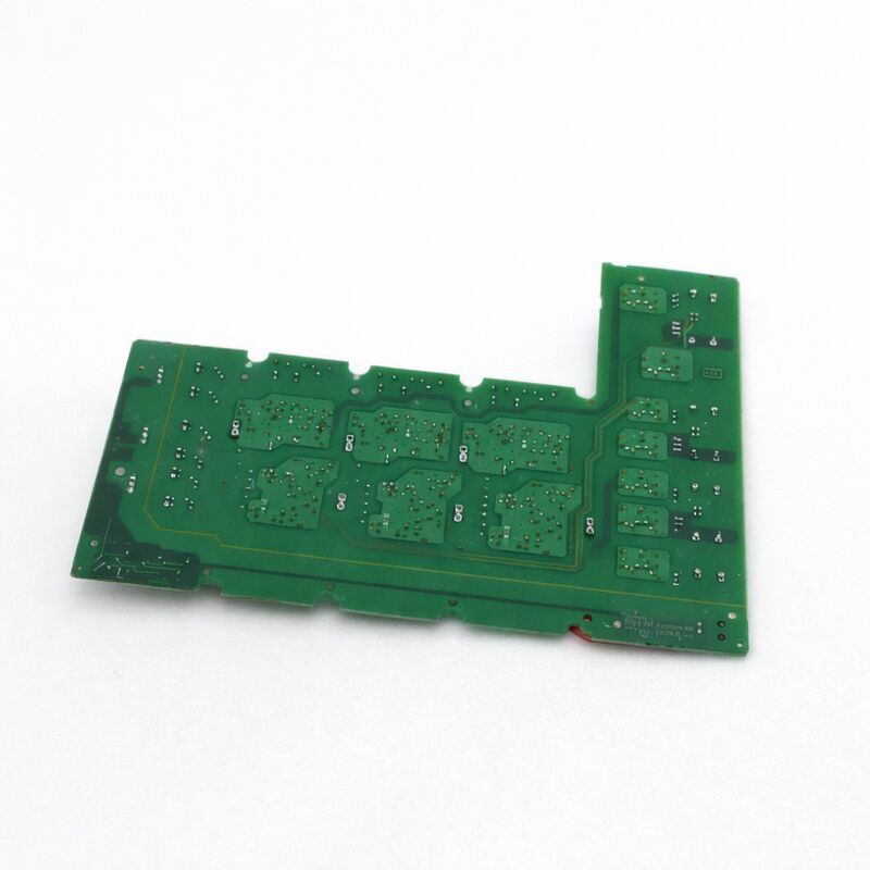
The A5E00825002 is the IGD1/R3-BGR drive board — the first-generation IGBT gate driver assembly complete with IGBT output modules — for Siemens MICROMASTER 440 and MICROMASTER 430 AC drives in the 110 kW class.
The board is the heart of the MM440's power section at this power level: it carries the gate driver circuitry that fires the inverter IGBTs, the current measurement path that feeds back into the drive's vector control algorithm, and the IGBT modules themselves that do the actual high-power AC switching.
The MICROMASTER 440 at 110 kW (6SE6440-2UD41-1FA1 and similar) is found in some of the most demanding continuous-duty industrial applications — large compressors, heavy conveyors, centrifuges, industrial fans, and process pumps where the drive runs close to rated power for extended periods.
At this power level, the physical size of the IGBT gate driver and module assembly increases significantly compared to lower-power MM440 variants.
The A5E00825002 reflects this: the R3-BGR form factor is a larger, more substantial assembly than the R-series boards used in smaller frame sizes.
The "BGR" suffix in the R3-BGR designation identifies the specific board revision for this IGBT and current rating combination.
It distinguishes this board from the closely related A5E00825001 — which serves the 210A variant at the same 480V/650VDC bus — confirming that the 260A rating is specific to the A5E00825002 and the two boards are not interchangeable.
Key Specifications
| Parameter |
Value |
| Part Number |
A5E00825002 |
| Manufacturer |
Siemens AG |
| Product Type |
Drive Board — IGD1/R3-BGR with IGBT Output Modules |
| Gate Driver Gen. |
IGD1 (first generation) |
| Form Factor |
R3-BGR |
| AC Input Voltage |
480V AC |
| DC Bus Voltage |
650V DC |
| Current Rating |
260A |
| IGBT Module |
FS450R12KE3-S1 (450A/1200V) |
| Drive Application |
MICROMASTER 440 / 430, ~110 kW class |
| Production Status |
Discontinued |
| Country of Origin |
Germany |
IGD1 — First-Generation IGBT Gate Driver
The IGD1 designation identifies this board as belonging to the first generation of Siemens' IGBT gate driver (IGD) series for SINAMICS and MICROMASTER drives.
The IGD1 generation established the fundamental architecture that later evolved into the IGD2 used in the SINAMICS S120 and SINAMICS G120 chassis platforms.
The IGD1 functions the same way as later generations: it receives PWM switching commands from the drive's control unit via fibre-optic links, generates the gate pulses for each of the six IGBT positions in the three-phase bridge, and monitors each IGBT for desaturation (overcurrent detection) via the gate driver's feedback path.
The fibre-optic link between the control board and the IGD1 provides galvanic isolation between the low-voltage control electronics and the high-voltage power section — at 650V DC bus, this isolation is essential for safety and for preventing high-frequency switching noise from propagating back into the control electronics.
The A5E00825002 incorporates the fibre-optic interface for this communication path as part of its PCB assembly.
FS450R12KE3-S1 IGBT Module at 260A
The FS450R12KE3-S1 is a complete three-phase IGBT bridge module rated at 450A continuous (1200V VCES), used in the A5E00825002 at a derated 260A operating current. This derating is deliberate — operating the module below its peak current rating extends thermal life, reduces junction temperature excursion during load transients, and provides margin against momentary overloads during the MM440's 150% overload capability at 60-second intervals.
At 480V AC input, the DC bus sits at approximately 650V DC.
The 1200V VCES of the FS450R12KE3-S1 provides adequate voltage margin at this bus voltage, accounting for the turn-off voltage spikes generated by the drive's output reactor and cable inductances.
Siemens specified the 1200V device for this bus voltage precisely because the safety margin at the drive's rated output conditions is required for long IGBT service life.
F022 Fault and the A5E00825002
The MM440 fault code F022 — indicating a fibre-optic interface fault between the control board and the IGD board — is one of the most common fault codes associated with the A5E00825002 in service.
When this fault appears in a 110kW MM440, the drive's control board has lost communication with the gate driver board via the fibre-optic connection. Before replacing the board, inspect the fibre-optic cables between the A5E00825002 and the control board: check for broken fibres, contaminated connectors, or cables that have been bent tightly enough to crack the fibre.
A damaged fibre is far more common than an actual board failure as the cause of F022.
If the fibre connections are intact and F022 persists, the gate driver circuitry on the A5E00825002 itself has failed and board replacement is required.
FAQ
Q1: The MM440 110kW drive shows F022 (fibre-optic board fault). The A5E00825002 has been visually inspected and no physical damage is visible. What should be checked before replacing the board?
F022 with no visible physical damage is almost always a fibre-optic cable issue rather than a board failure. Remove each fibre-optic cable from the A5E00825002's connectors and from the control board's connectors. Inspect the cable ends under bright light — look for contamination, cracking of the plastic fibre jacket, or discolouration at the tip.
Test each cable's transmission with a simple LED source and detector if available. Replace any suspect cable. Reconnect and power up before concluding the A5E00825002 board has failed.
Q2: The A5E00825002 is rated at 260A but the FS450R12KE3-S1 IGBT is rated 450A. Why is there such a large difference?
The IGBT's 450A rating is its peak or absolute maximum collector current under pulsed conditions at a controlled case temperature. In the continuous, thermally constrained environment of a sealed drive cabinet, with the switching losses from PWM at the drive's carrier frequency and the drive's overload capability factored in, the practical continuous current from this module is substantially lower.
The 260A continuous rating of the A5E00825002 is the thermally sustainable output at rated ambient conditions for the MM440 drive chassis, accounting for all these factors. The headroom between 260A and 450A provides the margin for the drive's 150% overload and for module longevity.
Q3: Can the A5E00825002 (260A) board be used in an MM440 that originally had the A5E00825001 (210A) board?
No — the two boards serve different drive ratings (110 kW vs the lower-rated drive associated with 210A). The physical mounting may appear similar, but the gate drive configuration, current sensor calibration, and control interface parameters are matched to the specific drive they serve.
Installing a 260A board in a drive sized for the 210A board introduces a current measurement mismatch — the control board's current scaling will be incorrect, resulting in improper current limiting, false overcurrent faults, or under-protected IGBT operation. Always confirm the exact A5E number against the installed board's label before ordering a replacement.
Q4: When replacing the A5E00825002, is it necessary to also apply thermal interface material between the IGBT module and the heatsink?
Yes, without exception. The IGBT module makes intimate contact with the drive's aluminium heatsink across its base plate.
The thermal interface material — typically a phase-change compound or pad — fills the microscopic air gaps between the two surfaces, dramatically reducing the thermal resistance from IGBT junction to heatsink.
Without proper TIM, IGBT junction temperatures under full load can be tens of degrees higher than the heatsink temperature, easily reaching the module's absolute maximum junction temperature.
An overtemperature fault (F0004 in MM440) or premature IGBT failure will result. Follow Siemens' specified TIM application procedure during installation.
Q5: The drive previously ran at full 110kW load without issues. After a power outage event, the drive now shows F0001 (overcurrent) at any load level above 50%. Is this the A5E00825002?
An overcurrent fault threshold that drops after a power event — particularly at a specific load percentage — typically indicates that one IGBT position in the A5E00825002 has been partially damaged.
The IGBT may still conduct and switch but with a degraded VCE(sat) characteristic, causing it to desaturate at a lower current than before the event. The gate driver's desaturation detection circuit triggers F0001 when it detects this abnormal VCE(sat).
Full load reveals the fault because the current is high enough to trigger the degraded protection threshold.
An oscilloscope measurement of the three motor phase currents during the fault will typically show asymmetry on one phase — pointing to the specific damaged IGBT position before full board replacement is decided.

 Your message must be between 20-3,000 characters!