MC00160783M01 | Inverter CPU / IO Control Board — Industrial Variable Frequency Drive Systems
Part Number: MC00160783M01
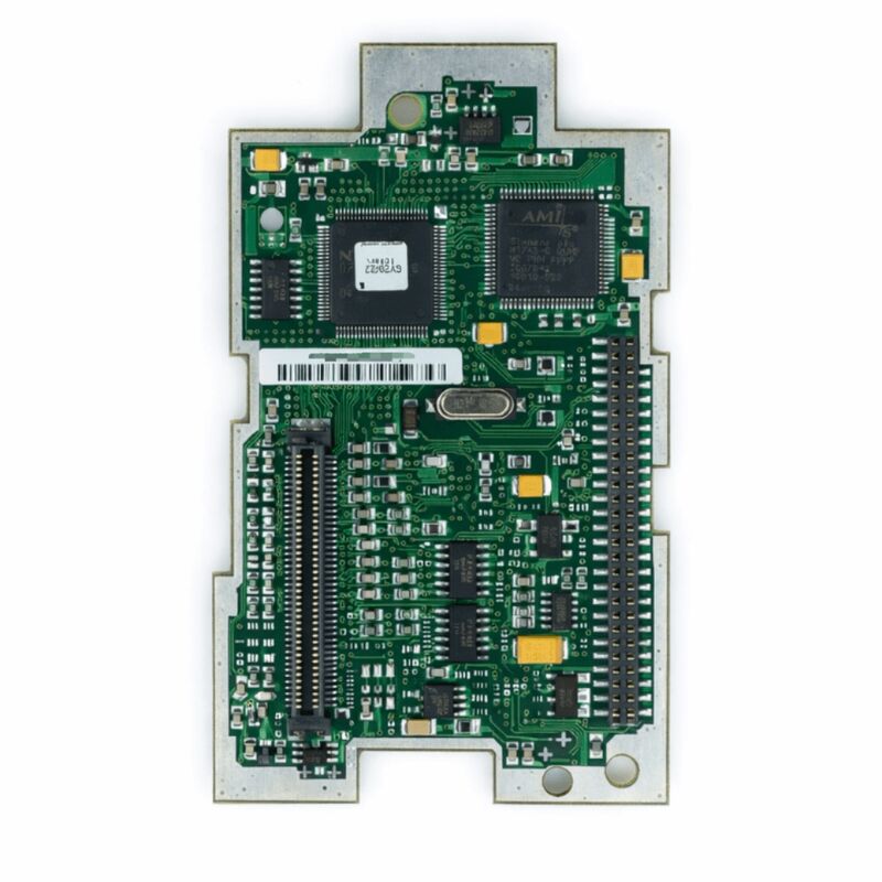
Product Type: Inverter CPU / IO Control Board (Integrated Control PCB)
Function: Central CPU and input/output interface control board for industrial frequency converter / inverter systems
Application: Industrial AC motor variable speed drives, frequency inverters, automation drive systems
Overview
The MC00160783M01 is an integrated CPU and I/O control printed circuit board designed for industrial variable frequency drive (VFD) and inverter systems. In the architecture of a modern industrial inverter, the CPU IO control board is the operational core: it brings together the drive's processor — which runs the motor control algorithms, parameter management, and communication protocols — with the input/output interface circuitry that connects the drive to the wider automation system.
On a single board, the CPU IO control card handles the real-time computation required for motor control and simultaneously manages the discrete and analogue signals that link the drive to sensors, actuators, PLCs, and operator panels.
Industrial frequency converters rely on the CPU IO board as their decision-making centre.
Speed references arrive from the plant control system. Feedback signals from motor current sensors, encoder feedback, and temperature monitors are processed. Control outputs for start, stop, forward, reverse, and fault relay go out through the IO interface. All of this passes through the MC00160783M01.
When this board fails, the drive typically loses all operational capability — it may power up but cannot accept commands, or it may not complete its self-test sequence at all.
The MC00160783M01 version designator M01 identifies this as the first version of this specific board, establishing its role in the drive's configuration baseline.
Industrial control boards of this type are designed to exacting reliability standards — they must operate continuously without interruption in industrial environments where vibration, temperature variation, and electromagnetic noise are routine.
Key Specifications
| Parameter |
Value |
| Part Number |
MC00160783M01 |
| Product Type |
Inverter CPU / IO Control Board |
| Function |
CPU processing and I/O interface for VFD systems |
| Application |
Industrial frequency converters / AC motor drives |
| Operating Temperature |
0 – 55°C (typical industrial standard) |
| Signal Interface |
Analogue and digital I/O for drive control |
| Control Signals |
24V DC digital I/O (typical) |
Integrated CPU and IO Architecture
The MC00160783M01 integrates two functions that in earlier drive generations often occupied separate boards: the CPU and the IO interface. The CPU section executes the motor control algorithm — in modern drives this is typically a vector control or direct torque control algorithm that requires precise timing and high sampling rates.
The algorithm computes the required voltage vectors to apply to the motor based on the commanded speed or torque and the measured motor currents.
It generates the PWM switching commands that go to the drive's IGBT gate drivers, and it does so on a cycle time measured in microseconds.
The IO section handles the slower but equally important task of interfacing the drive to the plant environment.
Digital inputs receive signals from external sources: the PLC start command, the fault acknowledgement signal, the motor thermal switch input, the emergency stop loop. Digital outputs send status signals back to the PLC: drive running, at speed, fault, ready.
Analogue inputs take speed references from the process control system — typically 4–20mA current signals or 0–10V voltage signals.
Analogue outputs report actual motor speed or torque back to the DCS or SCADA system.
Combining both functions on the MC00160783M01 reduces the board count in the drive, simplifies the internal wiring, and improves signal integrity — the CPU and IO interface share a common ground reference without the inter-board signal path that separate designs require.
Motor Control Processing
The CPU on the MC00160783M01 performs real-time motor control at the rate the drive's modulation strategy requires. For a typical industrial inverter running at a switching frequency of 2kHz to 16kHz, the control cycle runs at the same frequency — the CPU must complete its full control loop calculation within one switching period.
At 4kHz switching frequency, that is 250 microseconds per control cycle.
Within that window the CPU reads ADC inputs, executes the control algorithm, updates the PWM duty cycles, and handles any communication requests.
The IO processor, running concurrently, scans the digital inputs at a rate fast enough to catch signals from the plant — a run/stop signal or a fault input must be detected within a few milliseconds to respond appropriately.
The analogue inputs are sampled at rates appropriate for the slowest process variable (typically speed reference at 10ms update rate) up to the fastest feedback signal (current feedback sampled at the control cycle rate).
Replacement Considerations
When replacing the MC00160783M01, the drive's parameter set — which stores all configuration data for the motor, the control mode, the IO assignment, the communication settings, and the protection thresholds — should be backed up from the drive before removal.
After installing the replacement board and powering on the drive, verify whether the drive's memory retains the parameter set (some drives store parameters in non-volatile memory on the board itself, while others store them in a separate memory module or in the Control Unit).
If the parameter set is stored on the replaced board, it must be reloaded from the backup before commissioning.
Jumper settings, DIP switch positions, and any hardware configuration switches on the original board must be transferred or matched on the replacement board before installation.
FAQ
Q1: After a lightning strike on the plant supply, the inverter no longer responds to any run commands. The power stage appears undamaged and DC bus charges correctly. Is the MC00160783M01 the fault?
Lightning-induced surge events commonly damage the control board's IO interface section — the digital input optocouplers and the analogue input protection circuits are the most exposed components.
If the drive powers up (DC bus charges, display lights) but does not respond to any input signals and does not generate motor output, the IO interface on the MC00160783M01 has likely been damaged.
Check for other indicators: a fault code on the display pointing to an internal hardware fault confirms board-level damage.
Q2: The drive's display is completely blank after power-on. The supply voltage is confirmed correct. Is the MC00160783M01 the fault?
A blank display with confirmed correct supply voltage suggests either the CPU board's internal power supply has failed, or the display communication between the CPU board and the display panel has been interrupted.
Before concluding the CPU IO board has failed, check the connecting cable between the board and the display panel — reseat it.
Also check any control power fuses on the board. If supply is reaching the board but the display remains blank, the CPU board requires replacement.
Q3: The drive runs the motor correctly in local manual mode but does not respond to remote command signals through the digital inputs. The IO wiring has been verified correct. What is the likely fault?
A drive that responds locally but not remotely with confirmed correct IO wiring suggests that the digital input section of the MC00160783M01 has a fault — the optocouplers for the remote command inputs may have failed while other circuitry remains functional.
Verify the parameter settings that select between local and remote control source — ensure the drive is configured for remote input control.
If settings are correct and the digital input LED indicators on the board do not illuminate when the remote signals are applied, the input optocouplers have failed.
Q4: A replacement MC00160783M01 has been installed. The drive runs but displays incorrect motor speed on the analogue output and the PLC is receiving wrong speed feedback. What should be checked?
Incorrect analogue output signals after board replacement are typically caused by a calibration offset in the analogue output section of the new board, or by a mismatch in the output range configuration parameters. Check the parameter settings for the analogue output range (0–10V or 4–20mA selection, and the output scaling).
If the parameters match the original configuration but the output is still incorrect, the analogue output circuit on the replacement board has a calibration or component issue that requires service.
Q5: The MC00160783M01 is described as version M01. If a replacement shows M02 or a later revision, is it safe to use?
Revisions of a control board within the same part number family are generally backward compatible — the M02 revision would include component updates or reliability improvements while maintaining the same functional specification and physical interface.
However, confirm with the drive manufacturer's documentation or spare parts catalogue that the M02 revision is listed as a direct replacement for M01 before installation.
Some revision changes involve firmware updates that affect parameter compatibility.

 Your message must be between 20-3,000 characters!