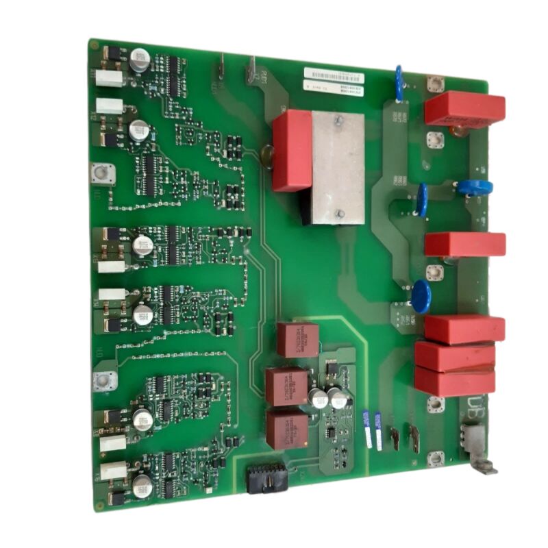
Siemens A5E00412608 | MICROMASTER 440 Inverter/Converter Trigger Board — IGBT Firing PCB for Drive Power Section
Part Number: A5E00412608
Alternate Reference: A5E00412705
Manufacturer: Siemens AG (Germany)
Product Type: Trigger Board — IGBT Firing PCB for AC Inverter/Converter Power Section
Product Family: MICROMASTER 440 (MM440)
Weight: ~490 g
Flame Rating: UL 94V-0
Production Status: Discontinued by Manufacturer
Country of Origin: Germany
Overview
The A5E00412608 is the trigger board — the IGBT firing printed circuit assembly — for the Siemens MICROMASTER 440 AC variable-frequency drive. It sits at the interface between the MM440's digital control electronics and the physical switching transistors in the drive's inverter power section.
Its primary task is straightforward but critical: receive pulse-width modulation commands from the control board and translate them into precisely timed gate pulses that actually switch the IGBT transistors on and off.
When this board fails, the drive's output stage goes silent — no switching, no voltage to the motor, no motion.
The MICROMASTER 440 was Siemens' multi-purpose AC drive platform covering 0.12 kW to 250 kW, and over its long production life it became one of the most widely deployed drives in industrial automation worldwide.
Conveyors, centrifuges, compressors, extruder lines, hoisting gear, packaging machines — the list of applications is almost as long as the list of industries that relied on MM440 drives.
Many of these installations remain productive today. Keeping them running requires reliable access to internal drive components like the A5E00412608, which is why a healthy aftermarket continues to serve sites long after Siemens discontinued the part.
The alternate reference A5E00412705 appears on boards of the same functional generation and is commonly listed alongside A5E00412608 in spare parts databases.
Both references address the same position in the MM440's power section, though confirming the specific number against the installed board's label remains the safest step before placing an order.
Key Specifications
| Parameter |
Value |
| Part Number |
A5E00412608 |
| Alternate Reference |
A5E00412705 |
| Manufacturer |
Siemens AG |
| Product Type |
IGBT Trigger / Firing Board |
| Product Family |
MICROMASTER 440 |
| Weight |
~490 g |
| Flame Rating |
UL 94V-0 |
| Production Status |
Discontinued |
| Country of Origin |
Germany |
What the Trigger Board Does — and Why It Matters
The MM440's inverter section uses a three-phase IGBT bridge to convert the drive's DC link voltage into the controlled AC voltage that the motor sees. Six IGBTs form this bridge — two per phase, arranged in upper and lower switch positions.
The trigger board generates the gate pulse for each of these six devices.
These gate pulses must be precisely timed. Even a small error in timing — a gate pulse arriving slightly early or late, or failing to arrive at all — causes immediate problems. Early firing of the wrong device creates a shoot-through condition: both the upper and lower switches in one phase conduct simultaneously, short-circuiting the DC link and generating a destructive overcurrent.
Missing pulses leave a motor phase undriven, creating asymmetric current waveforms, torque pulsation, and motor heating.
The A5E00412608 prevents these outcomes. The board includes desaturation detection circuits that monitor each IGBT during its on-state.
If an IGBT fails to saturate normally — indicating a current flow that the device cannot support — the board acts before the control software can respond, suppressing all gate pulses to protect the power section. This hardware response operates in microseconds.
UL 94V-0 Flame Rating
The UL 94V-0 rating of the board's substrate material is the highest classification in UL's vertical flame test series. Under test conditions, a UL 94V-0 substrate must self-extinguish within ten seconds of each of five flame applications, and must not drip burning particles.
This classification confirms that the A5E00412608 PCB material does not sustain or propagate combustion in the event of an internal fault or adjacent heat source.
In industrial drive cabinets where multiple boards, capacitors, and high-current conductors occupy a shared enclosed space, this rating is not a checkbox — it is a practical fire safety property that constrains how a localised fault can escalate.
ESD Handling Requirements
Gate driver ICs and optocouplers on the A5E00412608 are ESD-sensitive. Any handling outside of an ESD-controlled environment — bare hands on component areas, contact with plastic surfaces or synthetic clothing — risks damage that may not be immediately visible but shortens the board's service life or causes intermittent fault behaviour in service.
During installation or removal, use a grounded wrist strap, work on a conductive surface, and transport the board in anti-static metallised packaging.
The same precautions apply to the removal of the failed board — it should be packed correctly for return to a repair company if component-level assessment is planned.
FAQ
Q1: The MM440 triggers fault F022 (ground fault) at run command, but the motor and output cabling have been confirmed free of ground faults by insulation resistance testing. Could the A5E00412608 be generating a spurious fault signal?
F022 can originate from the trigger board if the board's current measurement circuitry is producing a false differential current reading.
The board's current sensors feed the drive's ground fault detection algorithm, and a drifted or failed sensor generates an apparent ground fault signature even on a healthy installation.
Verify the board's current sensor connections before replacing the board — a loose fibre-optic cable between the trigger board and control board is a common cause of spurious F022 trips.
Q2: The alternate part A5E00412705 is available but A5E00412608 is listed as out of stock. Are these interchangeable without any drive reconfiguration?
A5E00412705 and A5E00412608 are closely related boards for the same MM440 application. Multiple aftermarket suppliers list them as interchangeable replacements. However, Siemens' internal production history sometimes includes minor hardware revisions between closely numbered parts.
The safest step is to cross-check the drive's serial number and production date against the installed board's label before confirming interchangeability.
No drive parameter changes are required when replacing a trigger board — drive parameters are stored on the control board.
Q3: After installing a replacement A5E00412608, the MM440 runs but the motor current waveform shows a slight asymmetry on one phase. Is this a sign of a defective replacement board?
A minor asymmetry immediately after board installation sometimes reflects a residual current measurement offset in the new board's sensor circuit, which auto-corrects after the drive completes its first full load cycle.
If the asymmetry persists beyond the first few minutes of loaded operation, check the optical fibre connections between the trigger board and the control board — a partially seated fibre can introduce a phase delay on one gate drive channel that appears as current asymmetry in the motor output.
Q4: The A5E00412608 board has visible scorch marks on the gate drive area for one IGBT position. Is the root cause the board or the IGBT?
Scorch marks on a specific gate drive position almost always indicate that the corresponding IGBT experienced a fault that forced abnormal current back through the gate circuit. This is nearly always a sign that the IGBT failed first (short circuit or gate oxide breakdown) and damaged the trigger board as a consequence.
Before installing a replacement trigger board, test the IGBT power module — confirm that all six IGBT positions show normal gate-cathode resistance and no collector-emitter shorts.
Installing a new A5E00412608 on a drive with a failed IGBT will repeat the failure.
Q5: The MM440 with the A5E00412608 is being decommissioned. The trigger board is in perfect working condition. Can it be stored as a spare for another MM440 of the same frame size?
Yes — a confirmed-working trigger board from a decommissioned drive is a valuable spare for other MM440 units of the same power range.
Store it in conductive (anti-static metallised) packaging with a label showing the A5E part number, the drive model and frame size it was removed from, and the date of removal.
Keep it in a dry environment away from heat sources.
Before using it in a replacement installation, do a bench inspection under good lighting to check for any mechanical damage or corrosion on the connector area.
A board that has been stored correctly for years will typically commission normally.

 Your message must be between 20-3,000 characters!