FANUC A20B-1001-0120 | 6055 Series Digital AC Spindle Drive PCB — 200–240V, 3–30kW, Japan Origin
Part Number: A20B-1001-0120
Manufacturer: FANUC Corporation (Japan)
Product Type: Digital AC Spindle Drive Control PCB
Board Series: A20B-1001
Compatible Drive Series: A06B-6055-Hxxx (FANUC AC Spindle Servo Units, 6055 series)
Overview
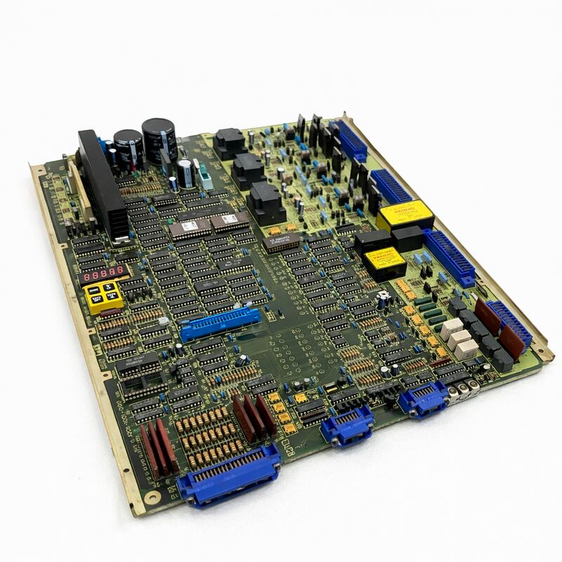
The A20B-1001-0120 is the digital control PCB fitted inside FANUC's A06B-6055 series AC spindle servo units. It sits at the top of the drive's internal structure — the control card that governs everything the spindle drive does.
This is the first generation of FANUC's digital spindle drive: the 6055 series replaced the earlier analog 6044 and 6052 drives, bringing digital closed-loop speed control and programmable spindle parameters to the machine tool spindle for the first time in this product line.
What digital means here is precise and important.
The analog spindle drives that preceded the 6055 received a variable DC voltage from the CNC — a higher voltage commanded a higher spindle speed. Speed regulation was achieved through an analog tachometer feedback loop.
The 6055 digital drive replaced this with a digital encoder feedback system: the spindle motor's speed is measured by a pulse encoder, and the A20B-1001-0120 compares the encoder count against the speed command in a digital loop running at high frequency.
The result is tighter speed regulation, better low-speed torque, and programmable acceleration/deceleration ramps — none of which were available in the analog generation.
The A06B-6055 drive units are recognisable by their anodized metal frame construction — the last generation of FANUC spindle drives to use that format before the later 6059 and 6060 series moved to different packaging.
These drives cover spindle motors from 3kW at the smallest end to 30kW at the top of the range, making the A20B-1001-0120 one of the most widely deployed spindle drive PCBs in the FANUC product history.
The drive units are found in a huge range of machines across the machining and turning centre market.
Key Specifications
| Parameter |
Value |
| Part Number |
A20B-1001-0120 |
| Manufacturer |
FANUC Corporation |
| Product Type |
Digital AC Spindle Drive Control PCB |
| Drive Series |
A06B-6055 (AC Spindle Servo Units) |
| Motor Coverage |
3 kW – 30 kW AC spindle motors |
| Input Voltage |
200–240V AC (switch-selectable) |
| Dimensions |
165 × 130 × 40 mm |
| Weight |
Approx. 1.2 kg |
| Cooling |
Fan or heatsink |
| Operating Temperature |
0 – 45°C |
| Storage Temperature |
−20 – 60°C |
| Manual Reference |
B-53425E |
| Common Alarms |
AL-02, AL-12, AL-17 |
| Board Versions |
/10E, /16F, /19F, others |
| Status |
Discontinued by Manufacturer |
Software Chips — Critical Installation Requirement
The A20B-1001-0120 carries socketed software chips that are specific to the drive's motor type, spindle configuration, and machine parameters. These chips include EPROM devices (which hold the spindle control software) and an NVRAM device (which stores the drive's learned parameters and orientation data).
This is the most critical aspect of the board replacement procedure.
When replacing this board, the software chips must be transferred from the original board to the replacement board before installation.
If a bare replacement board is installed without the original software chips, the drive may fail to initialise, run the spindle at incorrect speed, or generate immediate alarm codes on startup. The NVRAM chip carries the learned orientation angle and other runtime data — if it is transferred successfully, the spindle will likely restart without requiring full re-commissioning.
If the NVRAM has lost its data (due to battery failure or the chip itself failing), the spindle orientation will need to be re-learned.
The DAC chip, present on some versions of the board, provides the digital-to-analog conversion for the velocity reference.
If the original board had a DAC chip, it must be identified and transferred. Leaving the DAC chip socket empty in a board version that requires it will cause incorrect spindle speed behaviour.
Input Voltage Selection
The A20B-1001-0120 carries a voltage selection switch for 200V or 230V AC input. This switch must be set to the correct position for the machine's supply voltage before the drive is powered on. Using the 200V setting on a 230V supply — or vice versa — causes incorrect drive operation and may damage the drive's power components.
Before removing the original board, photograph or note the position of the voltage switch. Set the replacement board's switch to the same position.
Alarm Code Guide
The 6055 drive uses a 7-segment LED display on the A20B-1001-0120 to communicate alarm codes. The display is the primary diagnostic tool:
- AL-02 — Velocity control ready fault. The drive's speed control circuit has a fault condition. Check the motor encoder cable and encoder. If the encoder is confirmed good, the AL-02 can indicate a board fault.
- AL-12 — Overcurrent alarm. The motor output current exceeded the protection threshold. Verify motor winding insulation before concluding a board fault.
- AL-17 — Cooling fan alarm. The board's cooling fan has stopped or the drive's internal temperature has exceeded the shutdown threshold. Inspect and replace the fan if necessary.
FAQ
Q1: The 6055 spindle drive shows AL-02 on startup. The motor encoder has been confirmed good by a resistance check. Is the A20B-1001-0120 the fault?
AL-02 with a confirmed encoder is suspicious but not conclusive of a board fault. Also check the encoder cable for intermittent continuity — a resistance check may miss a hairline break in the cable that only opens under flexing.
Check the encoder connector pins at the drive's connector socket for poor contact or corrosion.
If cables and connectors are confirmed good and the alarm persists, the board's velocity control feedback circuit has likely failed and the A20B-1001-0120 requires replacement.
Q2: A replacement A20B-1001-0120 board arrived. The software chips have not been transferred yet. Can the drive be powered on briefly to test the new board before chip transfer?
No. Powering the drive with an unconfigured bare board will cause immediate alarm codes or incorrect spindle behaviour. In some cases it may corrupt the drive's operational state in a way that complicates subsequent commissioning.
Always complete the chip transfer before applying power. The correct sequence is: transfer EPROM chips, transfer NVRAM, set the voltage switch, match jumper positions to the original board, then power on.
Q3: The spindle runs at incorrect speed after the A20B-1001-0120 was replaced and all chips were transferred. What should be checked?
Incorrect speed with transferred chips usually means the DAC chip was either not present on the original board or was not transferred. Check the original board for a DAC chip socket — if the socket was populated, verify the DAC chip is correctly installed in the replacement board.
Also verify the voltage selection switch is in the correct position. If both are confirmed correct, check the jumper settings on the replacement board against the original — a mismatched jumper can alter the speed scaling.
Q4: The NVRAM chip was found to have failed on the original board (dead battery). Can the spindle be oriented correctly after replacement if the NVRAM data is lost?
Yes. Spindle orientation can be re-established after NVRAM failure. The 6055 drive's orientation system uses a one-rotation signal from the spindle encoder to find its reference point.
After clearing any orientation-related parameters that may have been corrupted, perform the orientation setup procedure from the FANUC B-53425E maintenance manual. This procedure commands the spindle to seek and lock on the orientation position.
The new NVRAM chip on the replacement board will store the learned position after the setup completes.
Q5: The 6055 drive and A20B-1001-0120 board are discontinued. Is replacement with a later-generation spindle drive feasible?
It is technically feasible in many cases. The 6059 and 6060 series spindle drives (which succeeded the 6055) use a different control interface — they are serial spindle drives rather than analog velocity command drives.
Upgrading from a 6055 to a serial spindle drive requires a CNC controller that supports the serial spindle interface, parameter reconfiguration on the CNC, and different wiring.
For machines whose CNC controller can support a serial spindle, this upgrade path extends the machine's service life significantly.
For CNC controllers that only support the analog velocity interface, the 6055 must be maintained.

 Your message must be between 20-3,000 characters!