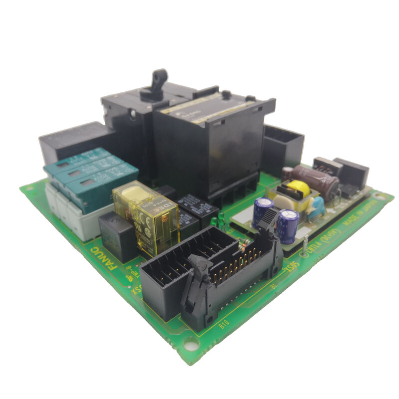
FANUC A20B-1001-0120 | AC Digital Spindle Drive Control PCB — For A06B-6055 Spindle Drive Series, 3 to 30kW, 200–240VAC, 165×130×40mm, 1.2kg, B-53425E
Overview
The FANUC A20B-1001-0120 is the control PCB for FANUC's first generation of digital AC spindle drives — the A06B-6055 series. This family of spindle drives marked a significant transition in CNC machine tool technology: moving from the earlier analogue DC spindle drives (where speed was controlled by an analogue ±10V signal) to digital AC drives with closed-loop digital speed and torque control, spindle encoder feedback, and on-board parameter storage.
The A20B-1001-0120 is the board that made this digital operation possible.
In the A06B-6055 drive, the control board (A20B-1001-0120) occupies the front-accessible position in the drive chassis — it carries the control microprocessor, the speed reference input circuitry, the encoder feedback processing circuits, the PWM signal generators for the IGBT base drivers, and the 7-segment alarm display that maintenance technicians use to diagnose faults without any other test equipment.
This front-mounted, user-facing design was intentional: FANUC engineers understood that maintenance access in production environments must be fast, and the LED alarm codes on the board face provide instant fault identification without opening the drive or connecting instrumentation.
The drive range covered by the A20B-1001-0120 spans model 1 through model 30 spindle motors — a range from approximately 3kW to 30kW output. The same control board serves this entire range because the motor-specific parameters (motor type, current rating, maximum speed, encoder resolution) are stored in an NV-RAM chip mounted on the board. Different drives in the A06B-6055 family are configured at the factory by programming this NV-RAM with the appropriate motor and drive parameters.
When replacing the A20B-1001-0120 board, the NV-RAM chip must either be transferred from the original board or the replacement board's NV-RAM must be programmed with the correct parameters from the maintenance manual.
Key Specifications
| Parameter |
Value |
| Compatible Drives |
A06B-6055-HXXX series |
| Spindle Power Range |
3–30kW (Model 1–30) |
| Input Voltage |
200–240VAC |
| Dimensions (L×W×D) |
165×130×40mm |
| Weight |
1.2 kg |
| Operating Temp |
0–45°C |
| LED Display |
7-segment alarm code |
| Manual |
B-53425E |
| Status |
Discontinued spare |
The Significance of "Digital" in Digital AC Spindle Control
The A06B-6055 series represented the move to digital spindle control at a time when "digital" carried real engineering meaning, not just marketing language.
The key advance over analogue predecessors was closed-loop digital speed regulation with spindle encoder feedback.
In an analogue DC spindle drive, speed regulation depended on the accuracy of tachometer generators and analogue circuits, with loop gains and response bandwidth limited by analogue component tolerances.
The digital AC system replaced the tachometer with a pulse encoder on the spindle motor, and the analogue speed regulator with a digital control loop executing in the control board's microprocessor.
The practical result: faster speed recovery after cutting load changes, better speed holding accuracy under varying spindle loads, and the ability to implement spindle orientation — stopping the spindle at a precise angular position for automatic tool change — in a way that was consistent and reliable rather than requiring the laborious tuning that analogue orientation circuits demanded.
Spindle orientation using the A20B-1001-0120's orient algorithm is initiated by the CNC through the orientation command (typically M19 in the part programme), and the drive precisely decelerates and positions the spindle at the encoder-defined orientation angle, ready for the ATC arm to engage the tool holder.
The A06B-6055 Series — Understanding the Drive Range
The A06B-6055 spindle drive family spans a wide range of spindle power ratings and voltage configurations, with each A06B-6055-HXXX model code corresponding to a specific motor model and current rating. Some frequently encountered variants:
A06B-6055-H002: One of the base models, confirmed to use the A20B-1001-0120 control board. A06B-6055-H103, H112, H118, H206: Further variants across the power range, all using the same A20B-1001-0120 control PCB — the board is common across the range, with drive-specific configuration stored in the NV-RAM.
The base section (power board) of each A06B-6055 drive differs by current rating and motor matching, but the control board is shared across the product family.
This commonality was a deliberate FANUC design decision that reduces the spare parts inventory required to maintain a fleet of A06B-6055 drives — a single type of control board, stocked in quantity, serves all drive sizes in the range.
LED Alarm Codes — On-Board Diagnostics
The 7-segment LED display on the A20B-1001-0120 face shows a two-digit alarm code when the drive detects a fault. These codes allow a technician to diagnose the fault category without any additional instrumentation:
AL-02: Motor speed detection fault — encoder signal absent or disrupted; suspect encoder cable, encoder power supply, or encoder hardware failure.
AL-12: Internal temperature excess — drive overtemperature; check cooling fan, ambient temperature, and duty cycle.
AL-17: DC link undervoltage — supply voltage problem or pre-charge circuit fault; check three-phase input.
The B-53425E maintenance manual provides a complete table of all alarm codes for the A06B-6055 series, their specific fault conditions, and the recommended diagnostic and corrective actions.
This manual is the primary reference for any A20B-1001-0120 service or repair activity and should be available to any technician working with these drives.
NV-RAM — The Critical Component for Board Replacement
The NV-RAM (non-volatile RAM) chip on the A20B-1001-0120 contains the drive's motor type registration and parameter set — the stored data that tells the control board which spindle motor it is paired with and what the operating limits, gains, and orientations are.
Every parameter accessible through the drive's front-panel buttons (MODE, UP, DOWN, DATA SET) is stored in this NV-RAM.
When replacing a faulty A20B-1001-0120 with a replacement board:
Option 1 — NV-RAM transfer: Carefully de-solder or use a chip extractor to remove the NV-RAM from the faulty board and install it on the replacement board. The replacement board then has exactly the original parameter set. This is only possible if the original board's NV-RAM is physically and electrically undamaged (which is usually the case if the board failure mode was a power supply or transistor fault rather than total electrical destruction).
Option 2 — Manual parameter entry: Using the B-53425E maintenance manual, enter all parameters manually through the drive's front-panel buttons.
This requires knowing the motor model number to identify the correct parameter table in the manual, then entering each parameter value individually.
The procedure takes approximately 30–60 minutes and requires careful attention to prevent entry errors.
FAQ
Q1: How is it determined that the A20B-1001-0120 PCB has failed, rather than the power board or the spindle motor?
Start with the LED alarm code on the board's face — it identifies the fault category.
Codes in the AL-02 through AL-07 range (encoder and speed detection faults) often implicate the encoder or its cable, not the control board.
Codes in the AL-12 through AL-17 range (temperature and power) may indicate power section issues.
A control board fault is more specifically suspected when: the drive shows no LED display at all (board not initialising), the alarm code does not correspond to any external condition, or the fault appears and disappears without any pattern correlated to load or temperature.
A board swap with a known-good A20B-1001-0120 (fitting the original board's NV-RAM) is the definitive diagnosis — if the alarm clears and the drive runs correctly, the original board was faulty.
Q2: The drive versions available include /10E, /16F, /19F suffixes. What do these mean, and does it matter which version is used?
The firmware revision suffixes (/10E, /16F, /19F, etc.) identify the version of the control software resident in the board's EPROM. Different firmware versions may have different alarm handling, parameter ranges, or feature sets.
For a like-for-like replacement, matching the firmware revision is preferable — the drive will behave exactly as the original. If the exact revision is unavailable, a later revision from the same A20B-1001-0120 family will generally operate correctly with the same NV-RAM parameters, but should be tested carefully after installation to confirm equivalent behaviour, particularly for spindle orientation angle and acceleration profile performance.
Q3: What are the most common causes of A20B-1001-0120 failure in long-service drives?
Electrolytic capacitor failure on the board's internal power supply is the most frequent age-related cause — capacitors degrade through electrolyte evaporation after 10–15 years, causing unstable power supply voltages that produce erratic alarm codes.
The transistor modules on the power section (not the control board) are more commonly the fault source for current-related alarms. On the control board itself, the NV-RAM chip can fail through data corruption from ESD or extended battery depletion, and the EPROM carrying the control firmware can fail through UV exposure or age-related bit decay.
A full refurbishment of the A20B-1001-0120 typically includes capacitor replacement, EPROM verification, NV-RAM backup, and functional test on a drive test rig with a spindle motor.
Q4: Is spindle orientation (M19) affected by the control board firmware version?
Yes. The spindle orientation algorithm — the calculation that decelerates the spindle and positions it at the commanded orientation angle — is implemented in the control board's firmware.
Different firmware versions (different EPROM contents) may have slightly different orientation response tuning. If spindle orientation accuracy or repeatability was acceptable before the board failure, installing a replacement with the same firmware revision and the original NV-RAM parameters should restore identical orientation behaviour.
If orientation performance changes after a board replacement with a different firmware revision, the orientation position adjustment parameters (accessible through the drive's front-panel buttons) may need fine-tuning.
Q5: What information should be prepared before sending a drive or board to a repair centre?
Before shipping, record: the complete drive model number from the nameplate (A06B-6055-HXXX), the control board part number and revision suffix (from the label on the A20B-1001-0120 itself), all parameter values from the drive (read through the MODE/UP/DOWN/DATA SET button sequence as described in B-53425E — typically 20–40 parameters), and the alarm code that was displayed when the fault occurred.
If possible, note whether the fault appeared suddenly or developed gradually, and whether it correlates with temperature (worst when hot, clears when cold) or load (appears under heavy cuts).
This information allows the repair centre to replicate the fault condition, test the repaired board under the same conditions, and confirm that the specific failure mode is resolved before return.

 Your message must be between 20-3,000 characters!