FANUC A20B-2003-0311 Spindle Motor Encoder — Aftermarket MZi Sensor for FANUC αi Series CNC Systems
Understanding What You're Actually Buying
The A20B-2003-0311 is the sensor PCB that forms the heart of the FANUC MZi-type spindle motor sensor assembly A860-2110-V001. These two part numbers are inseparable in practice: the A860-2110-V001 is the complete sensor unit — housing, rotor target, and PCB — while the A20B-2003-0311 is the specific circuit board installed within it. Most suppliers list both numbers together because when the sensor is ordered, the complete assembly ships. Whether you search by one designation or the other, you'll be looking at the same component.
This is a magnetic pickup feedback device — a 12-pin sensor used for speed measurement and spindle positioning on FANUC αi-series spindle motors. It replaces a failed or damaged original sensor and restores full closed-loop spindle control on the CNC machine it's fitted to.
What the MZi Sensor Does Inside a Running Machine
Every time a FANUC αi spindle motor turns, this sensor is producing data. It detects the rotation of a magnetic target wheel coupled to the motor shaft and converts that motion into a digital signal stream that the spindle amplifier reads continuously. From those signals, the amplifier knows two things: how fast the spindle is turning, and exactly where it is within each revolution.
Speed data keeps the closed-loop velocity controller working — the amplifier adjusts its output to match the commanded RPM regardless of cutting load changes, and the spindle holds its target speed without hunting or drooping. Position data enables something more demanding: rigid tapping and thread cutting, where the CNC must synchronize spindle rotation with Z-axis movement to produce accurate thread pitch. For that to work, the control needs to know the spindle's angular position within a single revolution, not just an average speed. The MZi sensor provides that positional resolution.
Lose the sensor — through contamination, PCB failure, connector damage, or mechanical impact — and the CNC loses both. Spindle alarms follow immediately. The machine won't run a spindle command, and for any threading operations, production stops until the sensor is replaced.
The Sensor Assembly: Physical Description
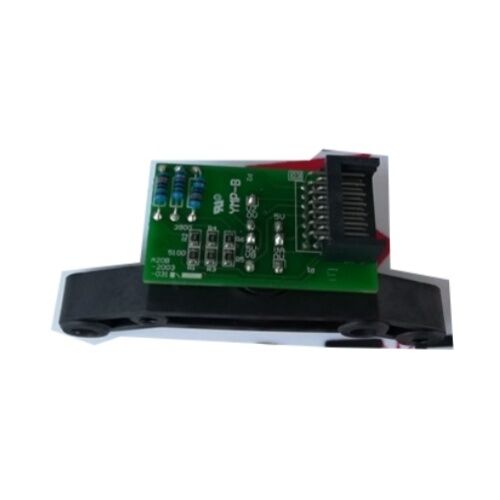
The A860-2110-V001 / A20B-2003-0311 sensor mounts to the rear of the FANUC αi spindle motor, positioned beneath the cooling fan assembly. The sensor housing contains:
- A magnetic target ring that mounts to the motor shaft extension and rotates with it
- The A20B-2003-0311 PCB, which holds the magnetic pickup elements and the signal conditioning circuitry
- A 12-pin connector interface for the feedback cable running to the spindle amplifier
The relationship between the target ring and the sensing PCB is a non-contact design — there are no brushes, no wear surfaces between the rotating and stationary elements. What degrades over time is typically the PCB itself (coolant ingress, vibration fatigue on solder joints, component aging) rather than any mechanical wear. This is what makes the sensor replaceable independent of the motor in most failure scenarios.
Aftermarket Replacement — The Practical Case
Original FANUC sensor assemblies carry substantial OEM pricing, often making a full machine downtime event more expensive than the repair truly needs to be. Aftermarket and compatible replacement units for the A860-2110-V001 / A20B-2003-0311 are manufactured to the same functional specification and serve the same feedback role within the spindle drive system.
The key word is compatible — not identical in every component, but electrically and mechanically equivalent where it counts. The 12-pin output interface, the signal format accepted by the FANUC αi spindle amplifier, and the physical mounting dimensions all match the original. When fitted correctly, the amplifier cannot distinguish a quality aftermarket unit from factory stock.
What matters when selecting an aftermarket sensor is whether the supplier has tested the unit against a live FANUC spindle drive under actual operating conditions — not just a static continuity check, but dynamic testing at representative spindle speeds. Static testing catches dead failures. Dynamic testing catches the more insidious problems: signal noise that only appears under rotation, miscounting at high RPM, marginal output levels that work at slow speeds but generate amplifier alarms at full cutting speed.
A note on the A20B-2200-0751: this is a newer FANUC part number that serves as the current replacement for the A20B-2003-0311 / A860-2110-V001 assembly. Both the original and its successor are cross-referenced widely in the market. If you are sourcing an aftermarket unit, confirm that the supplier's product is compatible with both designations before ordering.
Spindle Amplifier Compatibility
The A860-2110-V001 sensor is designed for use with FANUC αi-series spindle amplifiers, including the αiSP series that is standard equipment across a wide installed base of vertical machining centers, horizontal machining centers, and turning centers running FANUC Series 0i, 16i, 18i, 30i, and 31i controls.
The sensor connects to the spindle amplifier via the JY2 terminal, using the spindle feedback cable. This cable is a separate item — the sensor ships without cable in standard configuration, so if the cable is damaged, it must be sourced and replaced independently. Cable damage is worth checking before condemning the sensor itself; symptoms of a failing cable are identical to a failing sensor PCB from the CNC's perspective.
Recognizing Sensor Failure
The diagnostic picture varies depending on how the failure manifests:
Hard failure — sensor completely non-functional. The spindle amplifier loses all feedback signal on power-up. The CNC displays a spindle feedback alarm immediately, typically with an alarm code referencing speed deviation or encoder disconnection. No spindle commands will execute.
Intermittent failure — sensor degraded but still partly functional. The machine runs but exhibits spindle hunting (speed surges and recoveries at nominally constant RPM), rigid tapping errors where threads come out inconsistent in pitch, or alarms that clear on power cycle but return after the machine warms up. These thermal and vibration-dependent faults point strongly toward a degraded sensor PCB rather than a cable or connector issue.
Signal noise / contamination. Coolant that has entered the sensor housing can cause intermittent signal problems that don't produce a clean alarm — instead, the spindle amplifier reports occasional overcurrent or speed deviation faults that seem unrelated. If the machine environment involves heavy coolant exposure and the sensor has been in service for several years without inspection, this is a practical failure mode to consider.
Before ordering a replacement, check the feedback cable and its connector at both ends. A bent pin, corroded contact, or cracked cable jacket accounts for a meaningful percentage of apparent sensor failures. If the cable tests clean and the symptoms persist, the sensor assembly is the next step.
Installation Points Worth Knowing
The target ring alignment relative to the sensor PCB face requires attention during installation. Too large a gap between the target and the sensing face reduces signal amplitude; too small risks contact damage when the motor shaft has any axial play. Follow the motor's service documentation for the specified clearance when fitting the sensor.
The 12-pin connector should be cleaned and inspected at sensor replacement time — not just plugged in. Residual contamination from the old failed unit, or oxidation that has built up in the connector contacts over years of service, can cause the new sensor to exhibit the same symptoms as the old one.
Torque the sensor mounting hardware to specification. Loose mounting allows vibration to affect the sensor-to-target gap dynamically, producing the kind of intermittent noise that is extremely difficult to diagnose once the machine is back in service.
Frequently Asked Questions
Q1: What is the relationship between A20B-2003-0311 and A860-2110-V001 — are they the same part?
They are not identical but they describe the same sensor assembly when ordered as a complete unit. The A860-2110-V001 is the full MZi spindle motor sensor assembly — the housing, rotor target ring, PCB, and connector combined. The A20B-2003-0311 is specifically the PCB mounted inside that assembly. In practice, most suppliers ship the complete sensor (A860-2110-V001) when either part number is ordered, since the PCB is technically not sold separately as a standalone item. Both cross-references appear in listings for the same product because buyers often search using whichever number is visible on the failed unit or in the machine's parts documentation.
Q2: Is A20B-2200-0751 a direct replacement for A20B-2003-0311 / A860-2110-V001?
Yes. The A20B-2200-0751 is the updated FANUC part number that supersedes the A20B-2003-0311 / A860-2110-V001 assembly. It is functionally equivalent and fits the same motor mounting locations with the same 12-pin interface. If you're sourcing an OEM or aftermarket sensor and the supplier offers A20B-2200-0751 as an alternative to A20B-2003-0311, that substitution is valid. Confirm with the supplier that the unit has been verified against FANUC αi spindle amplifier systems before purchasing.
Q3: How do I know whether the sensor has failed or if the problem is in the feedback cable?
The most practical approach is to swap or test the cable first, since a cable is far less expensive than a sensor and cable faults cause identical alarm presentations. Disconnect the feedback cable at the spindle amplifier end and inspect the pins for corrosion, bending, or contamination. With a multimeter, check continuity of each conductor in the shielded cable from one end to the other — an intermittent open circuit typically reveals itself if the cable is flexed during testing. If the cable checks out clean, and swapping to a known-good cable (if one is available) doesn't clear the alarm, the sensor PCB is the most likely next failure point. Dynamic faults that only appear at speed and clear at rest are more often sensor PCB issues than cable faults.
Q4: Will an aftermarket replacement sensor work correctly with a FANUC 0i or 30i series control?
The sensor interfaces with the spindle amplifier — not directly with the CNC control. As long as the amplifier is an αi-series spindle amplifier (αiSP series) and the sensor provides the correct MZi-type signal format on the 12-pin output, the CNC series upstream makes no difference. FANUC 0i, 16i, 18i, 30i, and 31i controls all communicate with the αiSP amplifier through a serial interface; the amplifier in turn processes the raw sensor feedback internally. A quality aftermarket sensor that produces the correct signal will work transparently across all these control generations.
Q5: What handling precautions are needed when storing or shipping the sensor before installation?
The sensor PCB contains static-sensitive components and should be stored in ESD-protective packaging. The rotor target ring, though mechanically robust, can be affected by strong external magnetic fields — avoid storing the sensor near permanent magnets, transformers, or other magnetized components, as field exposure can affect the magnetic target's properties. Keep the assembly in its original packaging in a dry, stable-temperature environment; the connector pins are susceptible to corrosion in humid conditions. If the sensor is being returned as a defective unit for repair evaluation, ensure the connector is protected with a dust cap or wrapped connector cover during transit, as pin damage during shipping is a common cause of sensors arriving at repair facilities in worse condition than when they left the machine.


 Your message must be between 20-3,000 characters!