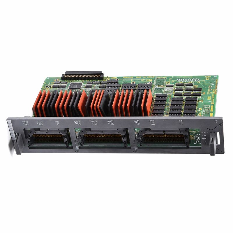
FANUC A16B-2200-0955 | Sink Type 104/80 I/O PCB Without Hi-Speed Skip — Series 16 / 18 CNC, Japan Origin
Part Number: A16B-2200-0955
Manufacturer: FANUC Corporation (Japan)
Product Type: Machine I/O PCB (Sink Type)
Board Series: A16B-2200
I/O Configuration: 104 Digital Inputs (DI) / 80 Digital Outputs (DO)
Output Type: Sink (NPN, current sinking)
High-Speed Skip: Not included
Compatible Systems: FANUC Series 16, 18 CNC
Overview
The A16B-2200-0955 is a high-capacity machine I/O board for FANUC's Series 16 and 18 CNC controllers, providing 104 digital inputs and 80 digital outputs in a sink-type output configuration without the high-speed skip function.
It is the physical interface between the CNC controller's PMC logic and the machine tool's electrical devices — every sensor, switch, and actuator that the machine's automation system uses connects to or through this board.
Compared to the A16B-2200-0956 (which provides 72 digital outputs), the A16B-2200-0955 adds 8 more output channels, bringing the total to 80.
This additional capacity makes it better suited to machines with more controlled outputs — machines where the original 72-output count was not sufficient.
More relay coils, solenoid valves, indicator lamps, or auxiliary motor contactors can be accommodated within the same board form factor.
The board's 104 input channels and 80 output channels are organised in groups and mapped to specific PMC I/O address ranges.
The PMC ladder program reads the input addresses to learn the machine's status and writes the output addresses to command machine actions.
The board makes these logical addresses real: when an input address reads 1, it means the corresponding field sensor or switch has asserted its signal; when an output address is written to 1, the corresponding output transistor switches on and drives its connected load.
Key Specifications
| Parameter |
Value |
| Part Number |
A16B-2200-0955 |
| Manufacturer |
FANUC Corporation |
| Product Type |
Machine I/O PCB |
| Board Series |
A16B-2200 |
| Digital Inputs (DI) |
104 |
| Digital Outputs (DO) |
80 |
| Output Type |
Sink (NPN / current sinking) |
| High-Speed Skip |
Not included |
| Field Voltage |
24V DC |
| Compatible CNC |
FANUC Series 16, 18 |
| Origin |
Japan |
| Operating Temperature |
0 – 55°C |
| Storage Temperature |
−20 – 60°C |
| Condition Available |
New (surplus) / Refurbished / Repaired |
104 Inputs — Machine Sensing Coverage
A machine tool with full automation — automatic tool change, pallet change, workpiece clamping, coolant systems, chip conveyor, sliding doors, and multiple safety interlocks — can easily accumulate 80 or more discrete input signals that the PMC needs to monitor.
Limit switches confirm axis positions. Pressure switches confirm hydraulic pressure. Reed switches confirm tool magazine positions.
Door-closed switches feed the safety interlock chain. Proximity sensors count pulley revolutions or detect part presence.
Each of these is a separate input channel on the A16B-2200-0955.
The board's 104 inputs provide capacity for this level of machine complexity with room for expansion.
The inputs are grouped to share common 0V references, which determines how field wiring is organised.
Maintaining correct grouping when rewiring or replacing the board is essential — mixing common references across input groups can cause cross-talk between inputs and spurious signal readings.
80 Outputs — Machine Actuation Capacity
The 80 output channels on the A16B-2200-0955 drive the machine's actuators. Each output is a transistor switch. When the PMC commands it on, the transistor conducts and completes the circuit through the connected device.
The output's current capacity determines what it can directly drive.
Within the board's rated output current, devices can be driven directly. Higher-current devices — large solenoids, motor starters — require an intermediate relay rated for the load current.
Output protection is important in field applications. Inductive loads — solenoid valves, relay coils — generate voltage spikes when switched off.
These spikes can damage the output transistor if not suppressed. Flyback diodes across inductive loads, connected so they conduct only during the spike, are standard practice.
A machine that repeatedly blows output channels often lacks adequate flyback protection on its inductive loads.
The A16B-2200 Series — I/O Variant Landscape
The A16B-2200 series offers I/O boards in several configurations to match different machine requirements.
The key differentiators are output count, output type (sink or source), and the presence or absence of the high-speed skip function.
The -0955 offers sink output with 80 DOs, while the nearby -0956 offers sink output with 72 DOs. The -0950 adds high-speed skip to the 104/80 sink configuration.
The -0986 is the source-type equivalent of the -0956 (72 DO, no skip).
Understanding this variant matrix is essential when sourcing a replacement.
Only the exact correct variant will work correctly in the original machine. The I/O count must match (otherwise some machine functions lose their PMC connections), the output type must match (sink/source), and the skip function must match the machine's functional requirements.
FAQ
Q1: After a maintenance period where the machine was powered off for two weeks, several output channels that were working before now fail to energise their loads. The PMC shows the addresses commanded ON. What happened?
Two-week power interruptions don't typically cause board damage by themselves.
The most likely cause for outputs that were previously good but now fail is a mechanical issue in the field wiring — connectors that loosened during maintenance work, or a field device that failed independently.
Trace the non-working outputs back to their field connections. Check each connection and the field device itself.
If field wiring and devices test good and the PMC confirms the address is commanded ON, the board's output channel has failed — possibly coincidentally during the maintenance period.
Q2: The machine's PMC ladder was recently modified to use some previously unused I/O addresses. The new addresses don't respond. All other I/O works normally. Is this a board fault?
Newly assigned addresses that don't respond is more likely a parameter or ladder configuration issue than a board fault.
FANUC CNC controllers require I/O addresses to be assigned and enabled in the PMC parameters before they become functional.
Confirm the PMC I/O parameters include the new addresses and that they are mapped to the correct physical connector on the A16B-2200-0955.
The board's physical I/O channels correspond to specific parameter-defined address ranges.
Q3: The machine generates a "DI/DO link error" alarm intermittently. It appears more frequently during heavy cutting cycles than during idle or light cutting. What is the likely cause?
I/O link errors that correlate with heavy cutting indicate electrical noise is interfering with the I/O link communication.
During heavy cutting, motor currents, drive switching frequencies, and mechanical vibration all increase.
These generate more electrical noise in the machine cabinet. Inspect the I/O link cable — its routing, shielding, and connector contacts.
A cable that shares a conduit with power cables, or a shield that is not properly grounded at both ends, will pick up more noise during high-power cutting cycles.
Q4: One entire group of 16 or 32 inputs shows as active simultaneously regardless of field device state. Other input groups are normal. What does this pattern indicate?
An entire input group reading active regardless of field state strongly suggests the common reference for that group has been shorted to positive voltage somewhere in the field wiring. The inputs in a group share a common 0V reference.
If that common reference gets connected to 24V by a wiring fault, all inputs in the group appear active.
Disconnect the field connector for the affected group and test whether the problem persists — if all inputs in the group read inactive with the field disconnected, the fault is in the field wiring, not the board.
Q5: When comparing the A16B-2200-0955 and A16B-2200-0956, the -0955 has 80 outputs versus 72. What is the practical implication when replacing one with the other?
If the original board has 80 outputs and is replaced with a 72-output board, the 8 outputs that were connected to channels 73–80 on the original board will have no corresponding output on the replacement.
Those machine functions will be permanently disabled and their field devices will remain un-driven.
Conversely, if the original has 72 outputs and a replacement with 80 outputs is installed, the extra 8 channels are unused but cause no harm.
Always match the original board's output count exactly to avoid loss of machine function.

 Your message must be between 20-3,000 characters!