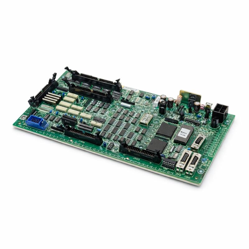
FANUC A16B-2201-0110 | Operator Panel I/O PCB — Series 16i / 18i / 21i (F16M/T), Japan Origin
Part Number: A16B-2201-0110
Manufacturer: FANUC Corporation (Japan)
Product Type: Operator Panel I/O PCB (Machine Panel Interface)
Board Series: A16B-2201
Compatible Systems: FANUC Series 16i, 18i, 21i (F16M/T)
Description: Machine Operator Panel Interface Unit
Overview
The A16B-2201-0110 is the operator panel I/O PCB for FANUC's Series 16i, 18i, and 21i CNC controllers — specifically the F16M and F16T machine operator panel configurations. This board is the physical and electronic bridge between the machine operator's panel hardware and the CNC controller's PMC (Programmable Machine Controller) logic. Every button press, switch selection, and indicator lamp on the machine's operator panel flows through this board.
The operator panel is where the human being meets the machine.
Feed rate override knobs, mode selector switches, axis jog buttons, cycle start, feed hold, single block — all of these physical controls are wired to the operator panel I/O board.
The board receives the electrical signals from these controls, converts them to digital states, and presents them to the PMC through its I/O interface.
In the return direction, the PMC's output logic — which drives the panel's indicator lamps and status displays — flows out through this board to the physical lamp circuits.
Without a functioning A16B-2201-0110, the machine's operator panel becomes inoperative.
The CNC may continue running internally, but the operator loses the ability to command the machine through the panel.
Equally important, critical panel inputs like the emergency stop button and the feed hold function route through this board — a failed panel I/O board can compromise the machine's ability to respond to operator safety commands through the panel.
Key Specifications
| Parameter |
Value |
| Part Number |
A16B-2201-0110 |
| Manufacturer |
FANUC Corporation |
| Product Type |
Operator Panel I/O PCB |
| Board Series |
A16B-2201 |
| Compatible Systems |
FANUC Series 16i, 18i, 21i (F16M/T) |
| Application |
Machine operator panel interface |
| Input Voltage |
24V DC (field side) |
| Origin |
Japan |
| Operating Temperature |
0 – 55°C |
| Storage Temperature |
−20 – 60°C |
| Humidity |
75% RH max (non-condensing) |
| Condition Available |
New (surplus) / Refurbished / Repaired |
Panel I/O — The Hardware Interface Layer
The operator panel I/O board occupies a specific architectural position in the CNC system. The CNC controller's main CPU board handles program execution and motion interpolation. The PMC executes the machine's ladder logic.
The panel I/O board handles the electrical interface to the physical world of the machine panel.
Machine panels contain dozens or hundreds of individual push buttons, key switches, selector switches, and indicator lamps.
Each of these is a separate electrical circuit with its own wiring. Without the panel I/O board's organised input/output architecture, each of these circuits would require direct, individual connections to the CNC's logic circuits — an impractical arrangement in terms of noise immunity, wiring complexity, and distance.
The panel I/O board solves this by concentrating the panel wiring into a structured, conditioned interface.
The board's input circuits provide optical isolation between the field-side 24V DC panel wiring and the controller's logic circuits.
This isolation blocks noise and voltage transients that could travel from the panel wiring — which runs throughout the machine cabinet alongside power cables — into the controller's sensitive logic.
The board's output circuits drive the indicator lamp circuits.
These require more current than the controller's logic can supply directly. The output drivers on the panel I/O board bridge this gap, providing the current needed to illuminate the lamps while the controller's logic simply sets a digital output bit.
F16M/T Application Context
The A16B-2201-0110 serves the F16M (machining centre configuration) and F16T (turning centre configuration) of the Series 16i platform. This distinction matters because machining centres and turning centres have different operator panel layouts and different I/O requirements.
The M configuration includes specific inputs and outputs suited to the additional functions of a machining centre — tool change ready signals, spindle orientation inputs, pallet change signals. The T configuration addresses the different I/O requirements of a turning centre.
The A16B-2201-0110 boards the I/O requirements of these operator panel types, providing the right signal assignments and channel counts for the specific machine type.
Installing a board specified for a different machine type could result in incorrect I/O mapping even if the board physically fits and the connector types match.
Diagnosing Panel I/O Failures
Panel I/O board failures produce visible and immediate symptoms. Panel buttons that stop responding, indicator lamps that remain permanently lit or permanently dark regardless of machine state, mode selectors that appear to have no effect — these are all characteristic of a failing or failed panel I/O board.
The CNC's PMC diagnostic screens are the primary diagnostic tool.
These screens display the real-time state of every I/O address in the PMC. For a suspected panel I/O fault, the technician monitors the PMC input addresses corresponding to specific panel buttons while physically pressing and releasing each button. If the address changes state correctly, that input channel is functional. If it does not respond, the fault is in the board, the wiring, or the panel device itself.
Multiple input or output channels failing simultaneously — particularly channels that share the same connector group on the board — strongly suggests a board fault rather than wiring problems. Individual wiring faults typically affect one signal at a time.
Connector or board faults affect groups of signals simultaneously.
FAQ
Q1: The machine's cycle start button has stopped working. The CNC shows no alarm and otherwise appears normal. Could this be the A16B-2201-0110?
Check the PMC diagnostic screen for the cycle start input address while pressing the button. If the address changes state, the board is reading the button input correctly — the problem is in the PMC ladder logic or the CNC's mode conditions that gate the cycle start function.
If the address does not change state when the button is pressed, and the button's contact resistance is confirmed good with a multimeter, the board's input circuit for that channel has failed.
Q2: Multiple panel indicator lamps are permanently lit regardless of machine state. The PMC shows the output addresses for those lamps commanded to OFF. What is wrong with the board?
Lamps commanded OFF but permanently lit indicate the output driver circuits for those channels have failed in the conducting state.
The drivers should switch off when commanded by the PMC, but a failed driver remains conducting.
This is a board-level fault in the output driver section. The affected channels cannot be corrected by software changes — the board requires repair or replacement.
Q3: After a lightning event nearby, the panel completely stopped responding — no buttons work, no lamps illuminate. The machine otherwise starts normally. Is this the board?
Lightning events produce voltage transients that can damage the input protection circuits on boards connected to external field wiring.
The panel I/O board is directly connected to panel wiring that acts as an antenna for surge energy.
Input protection components may have been damaged while the board's other circuits remain intact. Inspect the board for visible damage.
If no damage is visible but the fault pattern — complete panel loss with normal CNC operation — is consistent, replace the board and test.
Q4: The replacement A16B-2201-0110 was installed. The panel now responds, but one specific button seems to have the wrong function. What could cause this?
Incorrect button function after board replacement usually indicates an I/O address mismatch — the PMC parameters or ladder logic that map physical I/O addresses to CNC functions may need to be verified.
In some configurations, the I/O address assignment is set through parameters or a connector configuration that must match the original board's setup.
Check the I/O address assignments in the PMC diagnostic screen against the machine's wiring documentation.
Q5: The board appears undamaged but the machine panel has always had one button that intermittently fails to register. Could this be the board or the button itself?
Intermittent single-button failure is more likely a panel hardware issue — a worn button contact, a connector with high resistance on that specific channel, or a damaged wire in the cable to that button — than a board fault. Board faults that produce intermittent behaviour tend to affect multiple channels.
Test the button's contact resistance directly. Inspect the wiring to that button. If wiring and contact test as good and the fault persists, the board's input circuit for that channel is marginal.

 Your message must be between 20-3,000 characters!