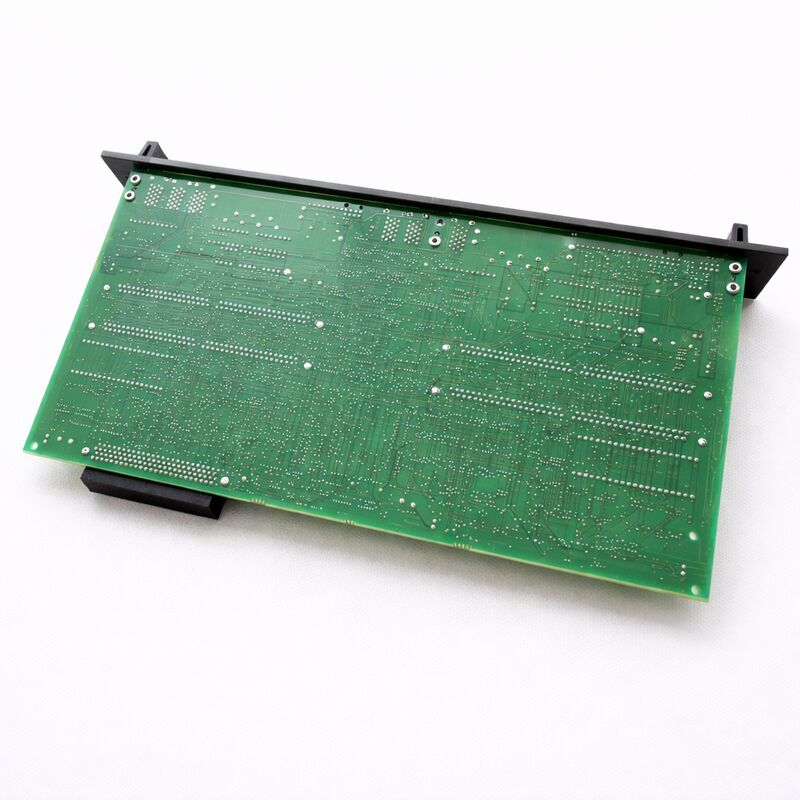
FANUC A16B-2202-0152 | SVUC2-4/12 Servo Amplifier Wiring Board — For A06B-6090-H223, Alpha Series Dual-Axis SVUC, A16B-2202 Power Circuit Board, Japan Origin
Key Specifications
| Parameter |
Value |
| Compatible Amplifier |
A06B-6090-H223 (SVUC2-4/12) |
| L-Axis Peak Current |
4 A |
| M-Axis Peak Current |
12 A |
| Amplifier Type |
SVUC (Type C interface) |
| Axes |
Dual-axis (L + M) |
| Control Board Partner |
A20B-2002-0032 (/03B or later) |
| CNC Interface |
Type C (Series 0C, 15-A/B, 16-A/B, 18-A, 21-TA) |
| Status |
Available — refurbished, tested |
| Origin |
Japan |
Overview
The FANUC A16B-2202-0152 is the wiring board for the SVUC2-4/12 — one of the dual-axis variants in FANUC's Alpha series SVUC amplifier family. The SVUC generation holds an important place in FANUC's servo amplifier history. It is the Alpha series variant using the Type C interface — a digital serial bus that predates the FSSB (Fibre-optic Serial Servo Bus) introduced in later Alpha and Alpha i generations.
For the machines that use it, the SVUC was a significant step forward from the analogue servo amplifiers it replaced, bringing digital servo control with improved axis coordination and tighter position loop closure.
The SVUC2 designation means dual-axis — this amplifier module drives two servo axes from a single module.
The 4/12 suffix specifies the peak current rating for each axis: 4A for the L-axis and 12A for the M-axis. This asymmetric pairing is deliberate.
A single module with different current ratings for each axis allows a machine builder to match the amplifier's power delivery to the actual requirements of each axis it drives — a smaller axis (perhaps a C-axis or a tailstock) paired with a larger feed axis (X, Z, or Y) in the same module.
The wiring board handles all the high-current physics inside the SVUC2-4/12. It connects to the DC bus from the SVUC power supply unit, switches the IGBT transistors that control motor current flow, senses actual motor currents, and routes motor phase voltages to the two sets of output terminals.
The companion control board (A20B-2002-0032) handles the digital intelligence — receiving Type C interface commands from the CNC, running the servo algorithm, and sending gate drive commands to this wiring board.
SVUC Wiring Board Function in the Amplifier Module
Inside the A06B-6090-H223 SVUC2-4/12 module, the A16B-2202-0152 wiring board handles functions that involve large currents and the physical connection between control electronics and the servo motors:
DC bus input. The SVUC unit's power supply section delivers rectified DC bus voltage to each SVUC servo module.
The wiring board terminates this bus connection and distributes the DC bus voltage to the IGBT transistor bridges for both axes.
Dual IGBT switching. Two independent IGBT bridges — one for the L-axis (4A) and one for the M-axis (12A) — switch motor current under command from the control board's gate drive outputs. The IGBT blocks for each axis are sized to their respective current ratings.
The L-axis bridge handles lighter current than the M-axis bridge, but both must switch reliably across the full operating current range.
Current sensing. Current sensing elements on the wiring board measure actual motor phase currents for each axis. These measurements feed back to the control board's servo algorithm, which closes the current loop to maintain commanded torque.
Accurate current sensing is fundamental to servo performance — any degradation in sensor accuracy directly affects position and velocity control quality.
Dual motor output terminals. The wiring board provides two sets of motor phase output connections — one for the L-axis motor and one for the M-axis motor.
Each set carries the full rated current for its axis, requiring appropriate terminal sizing and insulation.
SVUC vs Later Alpha Amplifier Generations
Understanding the SVUC's position in FANUC's amplifier history helps set expectations for maintenance and replacement parts supply.
The SVUC generation (Alpha series, Type C interface) was deployed with FANUC CNC systems from the late 1980s through the mid-to-late 1990s.
Machines from this era may still be operating in production — often on legacy production lines where the parts they make have not changed, and the machine toolpath is a validated production asset that makes machine replacement economically unattractive.
After the SVUC generation, FANUC introduced the SVU (Alpha series, Type A/B interface) and then the SVM (Alpha i series, FSSB interface).
These newer generations are not interchangeable with the SVUC — the Type C interface uses a different communication protocol and physical connector to the Type A/B interface, and neither is compatible with FSSB.
A machine wired for SVUC cannot use SVU or SVM amplifiers without also replacing the CNC main board and all servo cabling.
This means the A16B-2202-0152 wiring board — and the SVUC2-4/12 amplifier it belongs to — has a stable replacement parts market.
The machines that use it cannot use newer amplifiers without major retrofitting, so the SVUC spare parts ecosystem continues.
FAQ
Q1: The SVUC2-4/12 amplifier shows a servo alarm on the M-axis but the L-axis is working normally. Does this indicate the A16B-2202-0152 wiring board has failed?
A single-axis alarm with the other axis functioning normally narrows the fault to the M-axis's hardware chain.
The wiring board handles both axes, but each axis's IGBT bridge and current sensing circuit is independent.
If the alarm is an IPM (overcurrent or overtemperature) fault, the M-axis IGBT bridge on the wiring board may have failed. If the alarm is a position or velocity error, the fault is more likely in the M-axis motor, encoder, or cabling.
Confirm the alarm code against the FANUC Alpha series maintenance manual before concluding the wiring board is at fault.
Q2: Can the A16B-2202-0152 be serviced at component level rather than replaced as a complete board?
Component-level service is possible for qualified specialists. The wiring board's most common failure modes involve IGBT modules (for overcurrent failures) and electrolytic capacitors (for thermal aging).
Both are replaceable at component level if the correct replacement components are available.
Current sensing resistors can also fail and are replaceable.
For facilities with access to FANUC-qualified repair technicians and appropriate test equipment, component-level repair is often more economical than full board replacement for the SVUC generation, where complete replacement boards from the secondary market can be scarce.
Q3: The SVUC2-4/12 was replaced as a complete unit, but the old wiring board appears undamaged. Can it be transferred to a new shell unit?
Yes, provided the replacement shell's architecture matches the original.
The wiring board (A16B-2202-0152) and control board (A20B-2002-0032) are the functional components of the SVUC2-4/12 — the mechanical housing and bus connectors provide the structure.
If a new shell unit with the correct mechanical architecture is available, the functional boards can be transferred.
Ensure the control board revision level is /03B or later, as specified in FANUC's parts documentation for this amplifier configuration.
Q4: What is the Type C interface on the SVUC, and how does it differ from FSSB used in newer FANUC amplifiers?
The Type C interface is a digital serial communication bus used between FANUC CNC controllers and the SVUC servo amplifier generation.
It uses a multi-conductor cable connector (typically the CX5 or similar Type C connector on the CNC side and the corresponding connector on the amplifier).
FSSB (Fibre-optic Serial Servo Bus) replaces the copper cable with an optical fibre link, providing higher bandwidth, electrical isolation, and immunity to electromagnetic interference.
The two interfaces are incompatible in both hardware (different connectors and cables) and software (different communication protocols).
A machine with SVUC amplifiers uses the CNC's Type C interface ports; these ports are not the same as FSSB optical ports.
Q5: How should the DC bus voltage be managed when replacing the A16B-2202-0152 wiring board?
The wiring board directly contacts the DC bus inside the SVUC2-4/12. Before opening the amplifier, the DC bus must be fully discharged.
After powering down the SVUC power supply unit, wait a minimum of five minutes before opening the amplifier housing.
Use a voltmeter to confirm the DC bus voltage has dropped below 30V before touching any component on the wiring board.
The DC bus capacitors in the power supply unit store energy that can cause serious electrical injury — never assume discharge is complete based on time alone; always verify with an instrument.
This precaution applies even when the mains supply has been isolated.

 Your message must be between 20-3,000 characters!