FANUC A16B-2202-0420 | Alpha Series PSM Servo Power Supply Wiring Board — For A06B-6077 PSM-5.5 and PSM-11 (Early Revision), 200VAC, Alpha Generation Drive Spare, Japan Origin
Overview
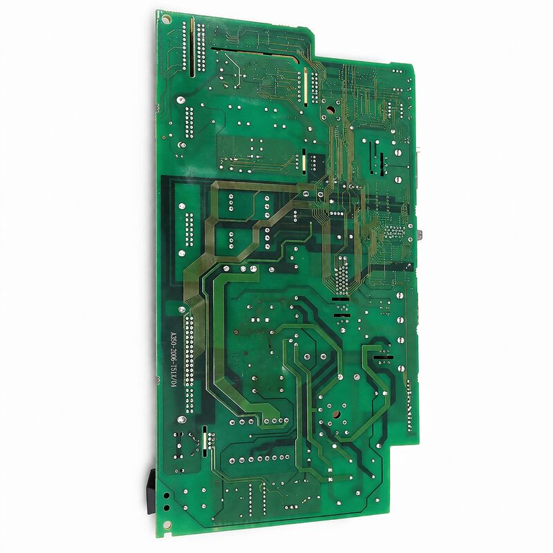
The FANUC A16B-2202-0420 is the power supply wiring board for FANUC's smaller-capacity Alpha generation PSM modules — the PSM-5.5 (5.5kW) and PSM-11 (11kW) in the A06B-6077 series.
These modules were designed for compact CNC machine tools where the total drive system power demand is modest: small CNC lathes with two servo axes and a relatively small spindle motor, compact machining centres with three axes and a mid-range spindle, or other specialised machines where the aggregate motor power fits within 5.5–11kW continuous.
The PSM-5.5 and PSM-11 fill the bottom of FANUC's Alpha series power supply range.
In a drive system context, the PSM's kilowatt rating represents the continuous power it can deliver to all connected servo and spindle amplifiers simultaneously.
A PSM-5.5 powering a 2-axis lathe with a 3.7kW spindle motor has roughly 1.8kW available for both servo axes combined — which is typically adequate for the smaller servo motors on compact lathes.
A PSM-11 covering three axes plus a 7.5kW spindle is a tighter configuration but still practical for machines with modest servo motor ratings.
The A16B-2202-0420 wiring board, like its counterpart the A16B-2202-0421, is a power-domain component — handling 200VAC three-phase mains input and converting it to the DC bus that the connected servo and spindle amplifiers draw from.
Its architecture follows the same principles: rectifier bridge, pre-charge circuit, regenerative inverter (or resistance braking in PSMR variants), and DC bus distribution.
The cross-reference from A16B-2202-0420 to A16B-2202-0421 at the revision 04C/05D boundary reflects FANUC's ongoing hardware refinement of the Alpha PSM series.
The -0420 is the older, earlier-revision board; the -0421 represents the updated design used in later-revision and higher-capacity modules.
Key Specifications
| Parameter |
Value |
| Compatible PSM Range |
PSM-5.5 (A06B-6077-H106), PSM-11 (A06B-6077-H111) |
| Input Voltage |
200VAC class, 3-phase |
| Revision Context |
Revision 04C and earlier |
| Companion Board |
A20B-1005-0591 (control board, early configuration) |
| Series |
A16B-2202 |
| Status |
Discontinued — spare available |
| Origin |
Japan |
Compact Alpha PSM Drives in the Field — Maintenance Context
The PSM-5.5 and PSM-11 were fitted to compact machine tools that were popular choices for small workshops and job shops during the 1990s and early 2000s.
A significant installed base of these machines continues to operate today — small CNC lathes producing turned components, compact vertical machining centres used for prototype and short-run production, and specialised machines like CNC grinding fixtures and engraving systems.
For these machines, the economics of maintenance are different from large, high-value production centres.
The machine tool's residual value may be modest, but its specific role in the production flow means downtime is still disruptive.
The A16B-2202-0420 wiring board — or more commonly the complete PSM module — is the component whose failure stops the machine entirely, making rapid availability of a tested replacement the priority.
The A06B-6077-H106 and H111 PSMs are physically smaller than the higher-capacity A06B-6087 modules, and their internal construction is correspondingly more compact.
This compactness means that component replacement within the module — particularly of the DC bus electrolytic capacitors — requires more care than on larger modules, but is not inherently more difficult for an experienced drive technician.
Common Failure Modes for Low-Power Alpha PSM Modules
DC bus capacitor aging: The electrolytic capacitors in the DC bus smoothing section age as a function of time, temperature, and operating hours. After 10–15 years of service, their capacitance decreases and their ESR (equivalent series resistance) increases.
The effect is increased DC bus ripple — the bus voltage oscillates more around its nominal value as the capacitors can no longer absorb current transients effectively. Symptoms include: unexplained occasional alarms during axes changes, PSM alarm codes appearing intermittently (particularly during high-demand moments like simultaneous axis acceleration), and reduced peak torque capability.
Pre-charge circuit component failure: The pre-charge resistor limits inrush current during power-up. If this resistor degrades (increased resistance) or fails open, the DC bus either doesn't charge or charges slowly.
If the bypass contactor or its driver circuit fails, the bus charges through the resistor permanently — which may work at light load but fails under demand. This produces a "PSM ready, but low bus voltage" condition that the CNC detects as a servo amplifier fault.
Rectifier component degradation: The rectifier diodes or thyristors that convert AC to DC can degrade over time, particularly if the machine's power supply has experienced voltage transients.
Degraded rectifiers produce lower-than-normal DC bus voltage or increased AC harmonic content on the bus.
A16B-2202-0420 vs A16B-2202-0421 — Choosing the Right Board
The key distinction between these two wiring boards is the PSM module they belong to, which is determined by the PSM module's revision level:
If the PSM module is an A06B-6077-H106 (PSM-5.5) or A06B-6077-H111 (PSM-11) — any revision — the applicable wiring board is the A16B-2202-0420.
If the PSM module is an A06B-6087-H115 (PSM-15) or larger — Revision 05D or later — the applicable wiring board is the A16B-2202-0421.
If the PSM module is an A06B-6087-H115 (PSM-15) Revision A (an earlier variant) — the applicable wiring board is the A16B-2202-0421 as well, but with the earlier revision control board configuration.
When the PSM module's complete revision history is uncertain, the safest approach is to replace the complete PSM module (housing, wiring board, and control board together) as a matched and tested unit from a specialist supplier, rather than replacing the wiring board in isolation.
FAQ
Q1: The PSM-5.5 module shows alarm LED "1" at power-up. Does this indicate the wiring board has failed?
LED "1" in FANUC Alpha series PSM diagnostics typically indicates a control power failure — the 24V control power input to the PSM has not been established.
This points to the external 24V supply or its wiring rather than the A16B-2202-0420 power wiring board. The wiring board handles the main circuit (AC to DC conversion), not the control power input.
Check the 24VDC supply to the PSM's control power connector before investigating the wiring board.
Q2: Can the A16B-2202-0420 be replaced with the A16B-2202-0421 in a PSM-5.5 or PSM-11?
These are different boards designed for different PSM models. While they share a common functional architecture, their component ratings, physical dimensions, and connector assignments are matched to their respective PSM housings.
Installing the -0421 board in an A06B-6077 PSM-5.5 or PSM-11 housing is not supported — the connector layouts and circuit configurations differ. Replace like-for-like: -0420 for -0420 in the A06B-6077 series.
Q3: The machine was running, then the PSM-11 suddenly shut down with an alarm. The machine was not under high load. What should be checked?
An unexpected shutdown under low load is often a thermal event — the PSM thermal protection has tripped because the internal temperature exceeded the threshold. Even at low motor load, the PSM generates heat in its own circuits.
Check the PSM cooling fan (if fitted): a seized or degraded fan is the most common cause of unexpected thermal shutdown in older PSM modules. Also check that the cabinet ventilation paths are not obstructed and that the ambient temperature inside the cabinet is within specification.
If the fan is operational and temperatures are normal, measure the DC bus voltage — a bus voltage outside specification (too high or too low) can also trigger protective shutdown.
Q4: Is the A16B-2202-0420 compatible with the PSM-15 in the A06B-6087 series?
According to FANUC's Alpha series documentation, the A06B-6087-H115 PSM-15 Revision B or later uses the A16B-2202-0421 wiring board (Revision 05D or later), while the Revision A variant uses the A16B-2202-0421 with earlier-revision control boards.
The A16B-2202-0420 is associated with the A06B-6077 PSM-5.5 and PSM-11 modules. Confirm the specific PSM module revision from its nameplate before selecting a replacement wiring board.
Q5: After PSM module overhaul with a replacement wiring board, the machine shows "SV alarm" on all servo axes at startup. What is the cause?
All-axes servo alarm at startup after PSM replacement usually indicates the DC bus has not reached operating voltage — the servo amplifiers wait for the DC bus to reach a threshold level before they will initialise.
This can happen if: the replacement wiring board's pre-charge circuit is faulty (bus doesn't charge), the PSM has not yet received the MCON (magnetic contactor control) signal from the CNC (which is required to complete the pre-charge sequence), or the AC line fuses for the PSM are not intact.
Measure the DC bus voltage directly at the bus bar in the PSM or at the SVM module — if it's below the expected operating level (normally around 270–300V DC for 200VAC input), the PSM pre-charge sequence has not completed successfully.

 Your message must be between 20-3,000 characters!