FANUC A16B-2202-0421 | Alpha Series PSM Servo Power Supply Wiring Board — For A06B-6087 PSM-15 Through PSM-55, 200VAC, Discontinued Industrial Drive Spare, Japan Origin
Overview
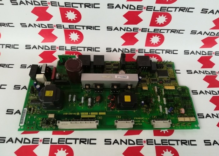
The FANUC A16B-2202-0421 is the wiring board for FANUC's A06B-6087 series Alpha PSM (Power Supply Module) — the component that determines how much electrical power is available to the servo and spindle drives in a FANUC CNC machine tool's drive cabinet.
Everything else in the drive system depends on the PSM functioning correctly: the servo amplifier modules cannot switch motor current without DC bus voltage, and the spindle amplifier cannot run the spindle. The PSM is genuinely the foundation of the drive system, and the A16B-2202-0421 wiring board is the PSM's power conversion heart.
The A06B-6087 PSM family covers the Alpha generation power supply modules from 15kW to 55kW continuous output (the "15" through "55" suffixes indicate kilowatt ratings).
This range — PSM-15 through PSM-55 — covers the majority of production CNC machine tools built through the 1990s and 2000s, from compact 2-axis lathes to large 5-axis machining centres with multiple high-power servo axes plus a powerful spindle motor.
The common wiring board across this range is the A16B-2202-0421, making it one of the most widely applicable boards in the Alpha drive service ecosystem.
The power regeneration design of the A06B-6087 PSM is a notable engineering characteristic.
When servo motors decelerate — stopping a heavy table or a fast-moving axis — the kinetic energy stored in that moving mass must go somewhere.
In a resistance-type power supply, this energy is burned off as heat in a braking resistor. In the regenerative PSM design using the A16B-2202-0421 wiring board, the servo amplifiers return this energy through the DC bus back to the PSM, which inverts it and feeds it back into the AC mains supply.
The result is a more energy-efficient drive system and elimination of the heat load from braking resistors — important in cabinets with limited cooling.
Key Specifications
| Parameter |
Value |
| Compatible PSM Range |
PSM-15 through PSM-55 (A06B-6087 series) |
| Input Voltage |
200–240VAC, 3-phase |
| Regeneration Type |
Power regeneration (returns energy to mains) |
| Revision |
Used from Revision 05D onwards |
| Series |
A16B-2202 |
| Status |
Discontinued — spare available |
| Origin |
Japan |
PSM Architecture — What the A16B-2202-0421 Wiring Board Contains
Inside the A06B-6087-H115 (PSM-15) to H155 (PSM-55) modules, the A16B-2202-0421 wiring board handles the physical power conversion. The board's primary circuits include:
Three-phase rectifier bridge: Converts the 200–240VAC three-phase mains input into raw DC.
The rectifier diodes or thyristors in this stage must withstand the full line-to-line voltage and the peak motor current demands of the entire connected drive system.
Pre-charge circuit: When the PSM powers up, the DC bus capacitors in the drive system are initially uncharged.
Charging them directly would produce very high inrush current. The pre-charge circuit — a resistor and bypass contactor arrangement on the wiring board — limits the charging current during power-up, then bypasses the resistor once the capacitors are charged to operating voltage.
The magnetic contactor (MCC) then closes to connect the full mains supply, and the PSM enters normal operation.
Regenerative inverter stage: The power regeneration circuitry takes regenerative current from the DC bus (generated by decelerating servo axes) and converts it back to AC for return to the mains. This involves a controlled inverter stage that must be synchronised to the mains supply frequency and phase.
DC bus distribution: The regulated DC bus voltage (nominally 300V DC for 200VAC input) is distributed via bus bars to all connected SVM and SPM modules in the drive rack.
The wiring board provides the bus connection points and the current path for this distribution.
Revision History — Why Revision 05D Matters
The A16B-2202-0421 is specified from Revision 05D onwards for the A06B-6087 PSM modules. Earlier revisions (04C and earlier) used the A16B-2202-0420 wiring board. The revision boundary at 05D/04C represents a hardware update in the PSM module — the updated wiring board (A16B-2202-0421) introduced improvements to the power conversion circuitry compared to the earlier -0420.
When sourcing a replacement, the revision of the PSM module determines which wiring board is correct.
Fitting a Revision 04C-era board into a Revision 05D-or-later PSM housing would produce an incompatibility in the interface connectors or the circuit configuration.
Always cross-reference the PSM module's revision marking against the wiring board specification before ordering.
DC Bus Safety — Critical Handling Requirement
The A16B-2202-0421 wiring board, like all PSM wiring boards, operates in a high-voltage environment. The DC bus that this board helps maintain runs at approximately 300V DC under normal operation — a lethal voltage.
Even after the mains input is disconnected, the DC bus capacitors (in the PSM and in the connected SVM/SPM modules) retain this charge for several minutes.
Any work involving removal or inspection of the A16B-2202-0421 wiring board must begin with a minimum waiting period after main power disconnection — typically the PSM's maintenance manual specifies 10–15 minutes — before the DC bus voltage can be assumed safe.
During this time, the "CHARGE" LED on the PSM face should extinguish, confirming capacitor discharge. Measuring the DC bus voltage directly with a suitably rated voltmeter before touching any internal components provides the definitive confirmation.
FAQ
Q1: The PSM shows a status LED code indicating a fault. How does the wiring board's failure relate to specific alarm codes?
The PSM's LED display (typically a 2-digit 7-segment) shows diagnostic codes that identify which subsystem within the PSM has failed. Codes related to the DC bus overvoltage or undervoltage, main circuit failure, or pre-charge circuit fault directly implicate the wiring board's power conversion circuits.
Codes related to FSSB communication or control power failure typically implicate the companion control board rather than the wiring board.
The Alpha series maintenance manual provides the full LED code interpretation table — always cross-reference the specific alarm code before determining which board has failed.
Q2: Can the A16B-2202-0421 from a PSM-26 be used in a PSM-37?
The A16B-2202-0421 is listed as the common wiring board across PSM-15 through PSM-55, which includes both the PSM-26 and PSM-37. If both modules are the same revision generation (05D or later), the wiring board is physically and electrically the same component and can be used interchangeably between these models.
However, the complete PSM unit's thermal design and cabinet installation are sized for each model's specific power rating — always verify the total kW output requirement of the machine's drive system against the PSM model's rated capability when replacing the whole module.
Q3: The PSM shows a "CHARGE" LED fault and the DC bus never reaches operating voltage. Is this the wiring board?
A failure where the DC bus never charges correctly is a strong indicator of a problem in the wiring board's pre-charge circuit or rectifier stage. Common causes include: a blown pre-charge resistor (which causes the bus to either not charge at all or charge very slowly), a failed bypass contactor driver circuit (which prevents the resistor from being bypassed after initial charge), or failed rectifier diodes (which produce a partial or zero DC bus).
Before concluding the wiring board has failed, verify the incoming AC voltage is within specification and the AC line fuses are intact — these external checks take minutes and eliminate the most common causes of DC bus failure.
Q4: What is the relationship between the A16B-2202-0421 wiring board and the recommended AC reactor?
For the PSM-15 (A06B-6087-H115), the recommended AC reactor is A81L-0001-0123. AC reactors are external components installed upstream of the PSM in the cabinet wiring — they reduce the harmonic currents drawn by the PSM's rectifier from the mains supply and limit the rate of inrush current.
The reactor is not part of the wiring board itself but works in conjunction with it. Reactors should always be present for PSM installations, and their absence or incorrect rating can cause increased stress on the wiring board's rectifier components, potentially accelerating failure.
Q5: The PSM wiring board appears physically damaged at the DC bus connection point. Can this be repaired at component level?
Physical damage at DC bus connection points — carbonised or burned bus bar connections, damaged copper traces, or failed current-carrying components in the bus path — can sometimes be repaired at component level by specialist FANUC repair facilities with appropriate high-current soldering and bus bar replacement capability.
However, the safety implications of a high-current bus connection repair require that any repaired board be thoroughly tested under full load before returning to service.
For PSM wiring boards, tested exchange units from specialist suppliers are often the more reliable and cost-effective solution compared to in-house component-level repair, particularly when the extent of damage is uncertain.

 Your message must be between 20-3,000 characters!