FANUC A16B-2202-0682 | Alpha SPMC-11 Spindle Amplifier Drive Board — αC Series, 48A, 283–325V DC
Part Number: A16B-2202-0682
Manufacturer: FANUC Corporation (Japan)
Product Type: Spindle Amplifier Power Wiring Board (Drive Board)
Board Series: A16B-2202
Overview
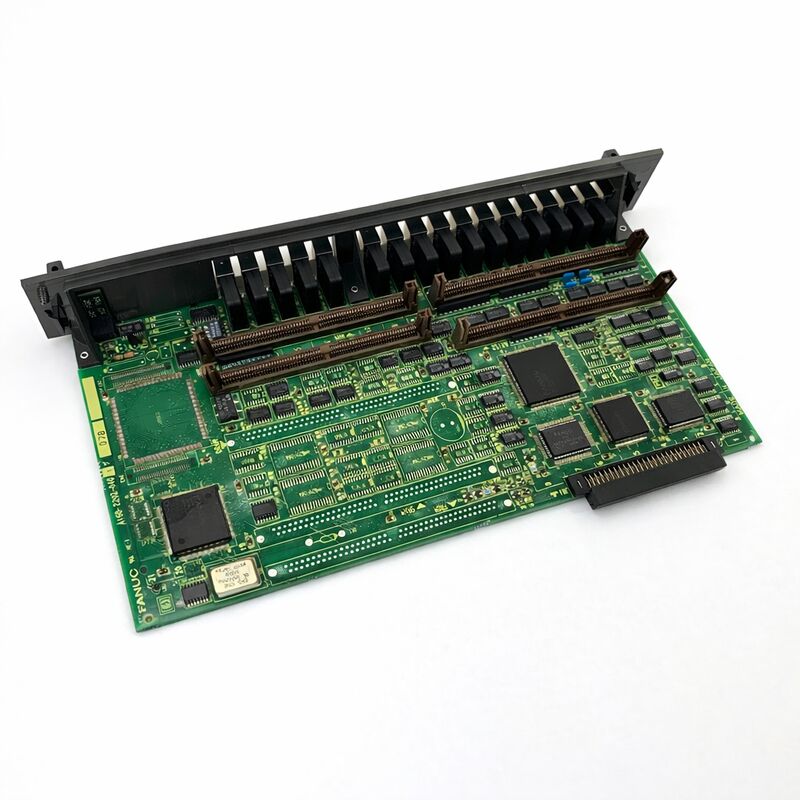
The A16B-2202-0682 is the power wiring board — the drive board — inside FANUC's A06B-6082-H211 Alpha SPMC-11 spindle amplifier module.
In the SPMC-11's two-board architecture, this is the power stage: the PCB that carries the high-current transistor circuitry, current sensing, and the physical power connections to the DC bus and the spindle motor.
The paired A20B-2001-0781 control PCB handles all the signal-level intelligence; the A16B-2202-0682 executes the current commands it receives.
The SPMC-11 (Spindle Amplifier Module C, 11kW) is part of FANUC's Alpha C spindle product line — a drive range designed for the compact machining centres, turning centres, and lathes that required a self-contained spindle amplifier in a narrow 90mm module format.
Found commonly in Leadwell CNC machines, FANUC Robodrill machining centres, and other compact machine tools, the SPMC-11 module drives αC6 and αC8 series AC spindle motors using Type 1 interface — the standard serial communication link between the CNC and the spindle drive.
The drive board's 48A rated output current corresponds to the SPMC-11's 13.2kW continuous rating. At the 283–325V DC bus voltage provided by the system's PSM (Power Supply Module), this board handles the switching transistor currents that generate the variable-frequency three-phase output driving the spindle motor.
The 90mm module width places the SPMC-11 among the narrower spindle modules — two internal cooling fans (one internal, one external) plus an external heatsink manage the thermal load within this compact footprint.
Key Specifications
| Parameter |
Value |
| Part Number |
A16B-2202-0682 |
| Manufacturer |
FANUC Corporation |
| Product Type |
Spindle Amplifier Power Wiring Board |
| Board Series |
A16B-2202 |
| Compatible Module |
A06B-6082-H211 (SPMC-11) |
| Associated Control PCB |
A20B-2001-0781 |
| Module Power Rating |
13.2 kW (30-min) |
| DC Bus Input |
283–325V DC |
| Rated Output Current |
48A |
| Compatible Motors |
αC6, αC8, αC-P8, αP12 |
| Module Width |
90 mm |
| Interface Type |
Type 1 (Serial) |
| Cooling |
Internal + external fans, external heatsink |
| Software Versions |
#H510, #H511, #H512 (incompatible) |
| Origin |
Japan |
| Status |
Discontinued |
SPMC-11 Architecture — Power Board Role
The SPMC-11 separates its electronics into two functional layers. The A20B-2001-0781 control board manages the spindle's closed-loop speed and torque control, processes feedback from the motor's position sensor, handles serial communication with the CNC, and generates the gate drive signals that the power board needs.
The A16B-2202-0682 receives these gate signals and uses them to switch its transistors, converting the 283–325V DC bus into the variable-frequency three-phase AC output that accelerates, runs, and decelerates the spindle motor.
This separation is architecturally deliberate. Spindle drives must handle very different demands: the spindle must accelerate from zero to maximum speed in seconds, maintain constant speed under varying cutting loads, and decelerate equally fast for rapid tool changes.
All of this requires the ability to switch very large currents — up to 48A in the SPMC-11 — with precision timing. Placing the high-current components on a dedicated power board keeps them physically separate from the more delicate signal-level control circuitry.
The power board's transistors also handle the regenerative braking cycle. When the spindle decelerates, the motor acts as a generator, returning energy to the DC bus. The SPMC-11's power board manages this bidirectional energy flow in coordination with the PSM.
Software Version Incompatibility
The SPMC-11 module is available in three software variants: #H510, #H511, and #H512. The suffix denotes the software version loaded in the control board's memory.
These versions are not interchangeable — they implement different feature sets and support different motor and feedback configurations.
The #H512 is the latest version and supersedes #H510 and #H511.
When sourcing a replacement module or arranging repair service, specifying the correct suffix is essential. A module with the wrong suffix suffix installed in a machine will typically produce alarm codes related to spindle parameter incompatibility or feedback configuration errors.
Before ordering, identify the suffix from the module's label and specify it to the supplier.
Fault Isolation — Power Board vs Control Board
When the SPMC-11 generates a spindle alarm, the alarm code's nature indicates whether the fault is in the power board or the control board.
Power board faults manifest as overcurrent alarms, IPM (transistor module) fault codes, or complete loss of spindle motor output.
Control board faults manifest as serial communication errors (C0, C1, C2 alarm codes), position coder signal errors, or parameter-related alarms.
The module's twin LED displays — one for each board section — are the first diagnostic reference.
FAQ
Q1: The SPMC-11 shows an overcurrent alarm (typically alarm code 12). The motor winding insulation has been tested and is good. Is the A16B-2202-0682 the fault?
If motor insulation is confirmed good and the alarm persists, the power board's transistor module is the most likely fault. Test by disconnecting the motor power cables (U, V, W) from the module and commanding the spindle. If alarm 12 now clears, the fault is in the motor or motor cable.
If alarm 12 still occurs with the motor disconnected, the transistor on the A16B-2202-0682 has likely failed. Module-level exchange or repair is the appropriate action.
Q2: A replacement SPMC-11 module with suffix #H512 is available, but the original was #H511. Is the #H512 a suitable replacement?
The #H512 supersedes the #H511 and is generally compatible as a replacement. However, verify the spindle motor type and feedback configuration against the #H512's supported combinations. In most standard αC6 and αC8 motor applications, the #H512 functions correctly as a direct replacement for #H511.
The #H510 is an earlier version that #H512 also typically supersedes, but always confirm with the machine builder's documentation for any application-specific feature differences.
Q3: The module's external cooling fan has stopped. Can the spindle continue in limited production while a replacement fan is sourced?
Operation without the external cooling fan should be avoided in anything other than the shortest intervals. The A16B-2202-0682's transistors generate substantial heat at the spindle currents involved in cutting.
Without the external fan, the heatsink temperature rises rapidly under load. Continued operation risks thermal destruction of the transistors.
A replacement fan should be sourced immediately, and production use of the spindle should be suspended until the fan is replaced.
Q4: The spindle alarm display shows C0, C1, or C2 codes. These are serial communication errors. Is the A16B-2202-0682 the cause?
C0, C1, and C2 alarm codes are serial communication errors between the CNC and the spindle module — they originate in the control board (A20B-2001-0781), not the power board.
First check the JA7B serial communication cable connection between the CNC and the SPMC-11.
Clean and reseat the connector. If the alarm persists, the control board is the suspect component, not the A16B-2202-0682.
Q5: The A16B-2202-0682 is not available separately from the complete module. What are the repair options when the power board specifically has failed?
Specialist FANUC drive repair providers offer transistor module replacement within the SPMC-11 module — replacing the specific failed IPM device rather than the entire module. This is a cost-effective option when the transistor has failed in isolation without catastrophic damage to surrounding circuitry.
For drives where the transistor failure has caused secondary damage, a complete module exchange is the more reliable path. Both options require the complete SPMC-11 module to be assessed by the repair facility.

 Your message must be between 20-3,000 characters!