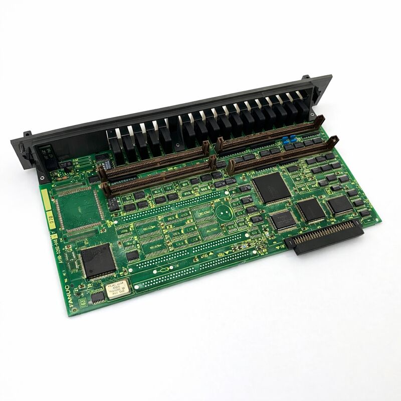
FANUC A16B-2202-0790 | Operator Panel I/O PCB — A16B-2202 Series, Series 16 / 18, Japan Origin
Part Number: A16B-2202-0790
Manufacturer: FANUC Corporation (Japan)
Product Type: Operator Panel I/O PCB
Board Series: A16B-2202
Compatible Systems: FANUC Series 16 / 18 CNC and compatible
Overview
The A16B-2202-0790 is an operator panel I/O printed circuit board from FANUC's A16B-2202 series. This board belongs to the cluster of I/O interface PCBs in FANUC's Series 16 and 18 controller ecosystem that connect the CNC controller's PMC ladder program to the machine tool's operator panel hardware.
The A16B-2202 series covers a well-defined range of these I/O boards — different variants serve different input/output channel counts and electrical configurations — and the -0790 is one variant in this established family.
The purpose of an operator panel I/O board is direct: it is the electrical interface between the human operator and the CNC controller.
When an operator presses a feedrate override button, selects a mode on the mode selector switch, or presses the cycle start button, those physical actions produce electrical signals.
The I/O PCB receives those signals, converts them to digital states, and presents them to the PMC's input registers. The PMC ladder program reads these inputs and responds by enabling the appropriate CNC functions or driving the appropriate machine outputs.
The return path is equally important. Every indicator lamp on the panel — the cycle running light, the spindle active indicator, the alarm light — is driven by the PMC's output logic. The output circuits on the I/O PCB take these logical output commands and convert them to the current that illuminates the physical lamps.
Key Specifications
| Parameter |
Value |
| Part Number |
A16B-2202-0790 |
| Manufacturer |
FANUC Corporation |
| Product Type |
Operator Panel I/O PCB |
| Board Series |
A16B-2202 |
| Compatible Systems |
FANUC Series 16 / 18 CNC and compatible |
| Application |
Operator panel digital I/O interface |
| Origin |
Japan |
| Operating Temperature |
0 – 55°C |
| Storage Temperature |
−20 – 60°C |
| Humidity |
75% RH max (non-condensing) |
| Condition Available |
New (surplus) / Refurbished / Repaired |
Panel I/O in CNC System Architecture
The relationship between the operator panel and the CNC controller is mediated entirely through the I/O PCB. This is by design.
The physical wiring from the panel — dozens or hundreds of individual conductors for switches, lamps, and selectors — does not connect directly to the CNC controller's main logic. It connects to the I/O PCB. The I/O PCB provides signal conditioning, protection, and the electrical interface that converts field signals to controller-compatible logic levels.
This separation serves several purposes.
The field wiring from the panel can carry noise, switching transients, and cross-coupling from nearby power conductors.
The I/O PCB's input circuits filter and debounce these signals so the PMC receives clean, reliable data.
The output circuits on the I/O PCB drive the relatively high currents required for indicator lamps — currents that would damage the controller's logic circuits if connected directly.
The PMC communicates with the I/O PCB over FANUC's I/O Link serial bus.
This serial connection means the physical distance between the controller cabinet and the operator panel is not constrained by the length of individual signal wires.
The I/O Link cable carries all channel data between the controller and the I/O PCB as a high-speed serial data stream.
The I/O PCB deserializes this data and drives the physical outputs accordingly.
Fault Patterns and Diagnosis
Operator panel I/O board faults are among the most operator-visible failures in a CNC system.
The panel is the primary interface between the operator and the machine. When the I/O board fails, the failure is immediately obvious: buttons stop responding, indicators show incorrect states, or the machine refuses to enter automatic mode because its safety interlock inputs are not being read correctly.
The CNC's PMC diagnostic screens are the primary diagnostic tool. These screens show the live state of every I/O address in the system.
An experienced technician monitors the input address for a specific panel button while physically pressing and releasing the button.
If the address changes state, the input circuit for that channel is functional. If it doesn't, the fault is in the board, the wiring, or the panel device itself.
Multiple input or output failures occurring together — especially in one connector group — strongly suggest a board fault rather than a wiring problem.
Individual wiring faults typically affect one signal at a time; board faults tend to affect multiple channels sharing a common input or output driver.
I/O PCB Selection — The A16B-2202 Family
The A16B-2202 series contains many variants serving different I/O channel counts and electrical types.
The variants are distinguished by their input count, output count, whether they include the high-speed skip (HDI) function, and their electrical type (source or sink).
Choosing the correct replacement requires knowing the exact part number of the installed board.
The -0790 variant serves its specific I/O configuration within the A16B-2202 family. Replacing it with a different suffix variant — even one with a similar channel count — risks incorrect electrical type or incompatible I/O address assignment.
Always source an exact part number match.
FAQ
Q1: The machine panel's mode selector and some pushbuttons stopped responding after a lightning event nearby. The CNC shows no alarms. Could the A16B-2202-0790 be damaged?
Lightning events can introduce voltage transients into control cabinets through the building's electrical supply or through long cable runs from the panel. I/O PCBs are directly connected to field wiring and can absorb transient energy from this path.
The input protection circuits may have failed, leaving the input channels non-functional even though the board is powered.
The CNC shows no alarms because the PMC is still running — it just isn't receiving the panel input signals.
Board replacement is the appropriate response.
Q2: Several indicator lamps on the panel are always lit, regardless of the machine's actual state. What could cause this on the A16B-2202-0790?
Permanently lit outputs with correct PMC logic state (PMC commanding the outputs off) indicate a failed output driver section on the board. The output drivers may have been damaged by a wiring fault, an overvoltage on the lamp supply, or simply component aging.
Verify the lamp supply voltage is within specification.
If it is correct and the PMC is commanding the outputs off, the output driver ICs on the board have failed. Replace the board.
Q3: The I/O Link connection between the controller and the A16B-2202-0790 shows a communication error alarm. The cable appears undamaged. What should be investigated?
An I/O Link communication error with a confirmed good cable can be caused by an I/O Link address conflict (if the board was recently replaced or reconfigured), a defective I/O Link interface circuit on the board, or a problem with the I/O Link interface on the controller side.
Check the I/O Link address setting on the board against the CNC's I/O assignment parameters.
If the address is correct and the alarm persists, the board's I/O Link interface circuit may have failed.
Q4: A maintenance technician recently worked inside the machine cabinet. Afterward, some panel functions were erratic. No visible damage is apparent. What happened?
Erratic panel functions after cabinet work typically indicate a partially unseated connector.
The technician may have accidentally disturbed a connector on the I/O PCB during work in the cabinet. Power off, locate the connectors on the A16B-2202-0790, and firmly reseat each one.
Also check for any cable that may have been accidentally disconnected or pinched.
In most cases, this resolves the issue without a board replacement.
Q5: The machine has a 0i-TB control, but the documentation lists the A16B-2202-0790 as a Series 16/18 board. Can it be used?
Compatibility with 0i-TB depends on the controller's I/O configuration. Some I/O PCBs from the A16B-2202 family are used across multiple FANUC controller generations when the I/O Link architecture and address range are compatible.
Confirm the specific board's compatibility with the 0i-TB configuration by checking the machine's electrical documentation or consulting a FANUC service reference.
Never install a board in a configuration where compatibility has not been explicitly confirmed.

 Your message must be between 20-3,000 characters!