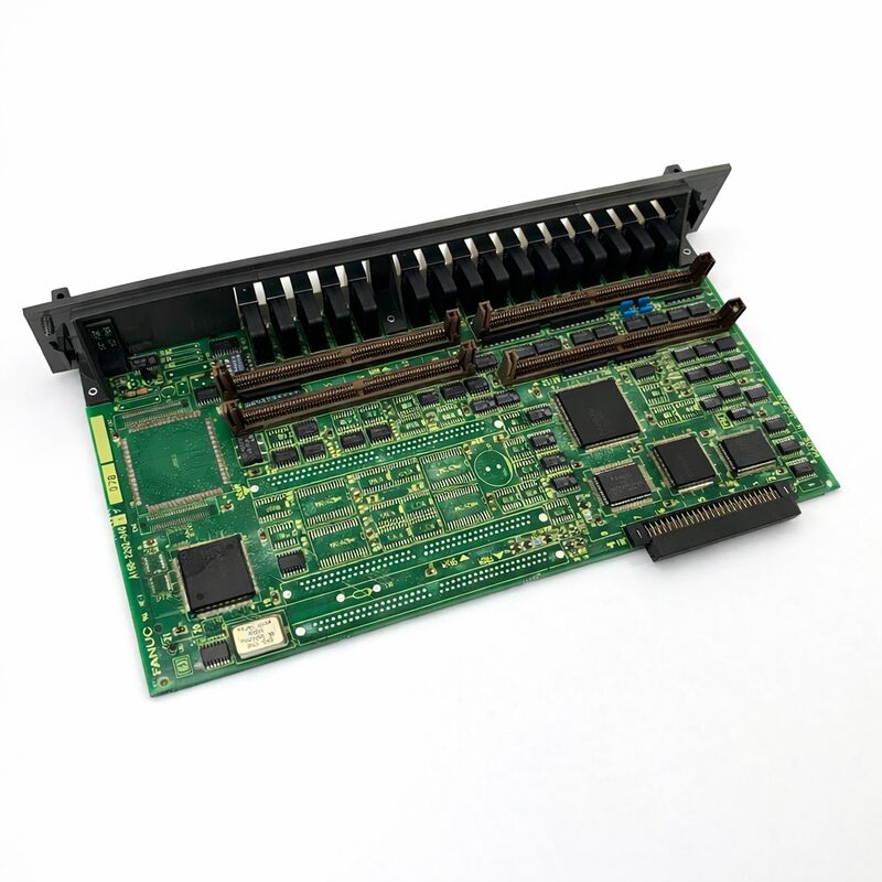
FANUC A16B-2202-0762 | Alpha SVM Servo Amplifier Wiring Board PCB — A16B-2202 Series, Japan Origin
Part Number: A16B-2202-0762
Manufacturer: FANUC Corporation (Japan)
Product Type: Servo Amplifier Wiring Board (Power Section PCB)
Board Series: A16B-2202
Application: FANUC Alpha series SVM servo amplifier modules
Function: Power stage PCB — transistor switching, current sensing, power connections
Overview
The A16B-2202-0762 is a wiring board — the power section printed circuit board — for FANUC's Alpha series SVM (Servo Amplifier Module) family. In the Alpha servo drive architecture, each SVM module contains two boards: the control PCB, which handles all the signal-level servo control processing, and the wiring board (also called the base board or power board), which houses the power transistors, current sensing circuits, and the physical connection terminals for the DC bus, motor output, and auxiliary signals.
The A16B-2202-0762 is the wiring board that serves its specific SVM module configuration within this architecture.
The A16B-2202 series is FANUC's wiring board family for the Alpha SVM range — a series of boards that covers single-axis, dual-axis, and three-axis servo amplifier modules across a wide range of current ratings.
Different boards in this series are paired with specific control PCBs to form complete servo amplifier assemblies.
The A16B-2202-0762 serves the high-current end of the single-axis Alpha servo module range, matched with the appropriate control card to form a complete high-power axis drive.
The wiring board's role in the SVM module is clearly distinct from the control card's role.
The control card thinks; the wiring board acts. The control card computes the current command and generates gate drive signals; the wiring board's transistors execute those commands, switching the DC bus voltage to produce the motor output current.
The current flowing through the motor — which may be tens of amperes — flows through the wiring board. The heat generated by this current, and by the switching losses in the transistors, must be conducted away through the module's heatsink — which is thermally coupled to the wiring board's transistor mounting surfaces.
Key Specifications
| Parameter |
Value |
| Part Number |
A16B-2202-0762 |
| Manufacturer |
FANUC Corporation |
| Product Type |
Servo Amplifier Wiring Board (Power PCB) |
| Board Series |
A16B-2202 |
| Application |
FANUC Alpha SVM servo amplifier modules |
| DC Bus Input |
283–325V DC (from PSM) |
| Function |
IGBT power stage, current sensing, power connections |
| Origin |
Japan |
| Operating Temperature |
0 – 55°C |
| Storage Temperature |
−20 – 60°C |
| Condition Available |
Via complete SVM module exchange or repair |
Alpha SVM Architecture — Wiring Board Function
The Alpha servo amplifier module's wiring board sits at the physical and electrical base of the drive. The DC bus connections — the high-voltage DC rails from the PSM that power the motor — terminate here. The motor output connections also terminate here.
The wiring board's IGBT transistors switch between these rails to generate the three-phase AC output that drives the servo motor.
Modern wiring boards in the Alpha series use IPM (Intelligent Power Module) devices that package the IGBTs and their gate drive circuits in a self-contained module.
Some boards use discrete IGBT devices. Regardless of the transistor technology, the switching function is the same: six transistors (in three pairs) control the three-phase output by switching each motor terminal alternately to the positive and negative DC bus rail.
The precise timing and duty cycle of these switches, commanded by the gate drive signals from the control card above, produces the sinusoidal three-phase current that the motor needs.
Current sensing on the wiring board measures the actual motor phase currents and reports them back to the control card.
The control card's current loop compares commanded to actual current and adjusts the gate drive duty cycle to minimise the error.
Without accurate current sensing, the closed-loop current control breaks down.
A16B-2202 Series in the Alpha Drive Context
The A16B-2202 series wiring boards span the Alpha SVM product range from the smallest single-axis modules through large-format high-current drives. Within this series, board numbers reflect the specific module they serve — the transistor current rating, the module physical size, and the drive configuration (single-axis, dual-axis, three-axis) all vary across the series.
The A16B-2202-0762 is matched to a specific SVM configuration in this range. Identifying the correct board requires the complete part number — different boards in the A16B-2202 series are not interchangeable, even if they appear physically similar.
The transistor ratings, thermal interface design, and connector layout are matched to the specific drive module they serve.
Wiring Board Faults — What They Look Like
When the A16B-2202-0762 fails, the symptoms are typically power-stage in character: overcurrent alarms, transistor fault alarms, missing output phase alarms, or in severe cases, complete drive shutdown from IGBT short circuit.
These fault signatures appear on the drive's LED display and are also reported as servo alarms to the CNC.
Control card failures, by contrast, produce control-related alarm codes — communication errors, VRDY failures, or parameter-related alarms.
Understanding this distinction guides the replacement decision: a power-stage alarm points to the wiring board, while a control alarm points to the control card.
Confirming this distinction saves the cost of replacing an undamaged board.
Service Approach — Module-Level Exchange
FANUC's policy and the standard practice of specialist servo amplifier service providers is not to supply the A16B-2202-0762 as a standalone board.
The Alpha servo module is serviced as a complete unit — through exchange (a refurbished, tested module for the faulty one), through drive-level repair where the specific fault is diagnosed and the failed component replaced, or through transistor module replacement when the IGBT device itself is the fault.
This module-level service approach exists because proper verification of the wiring board requires running it under motor load as part of the complete SVM module.
The transistors must be tested by actually switching motor current; the current sensing must be verified against motor current; the thermal path must be confirmed. None of these can be adequately verified on a bench without the complete module assembly and a connected motor.
FAQ
Q1: The SVM module's alarm display shows an overcurrent alarm on one axis. The motor winding resistance has been measured and is correct. Is the wiring board the likely fault?
An overcurrent alarm with a confirmed-good motor suggests either an IGBT fault on the wiring board (where a transistor has failed in a partially conducting state) or a current sensing fault (where the current sensing reports a higher current than actually flows).
Both are wiring board faults. Before concluding it is the wiring board, verify the DC bus voltage from the PSM is within the 283–325V specification — an overvoltage DC bus can cause overcurrent alarms without any wiring board fault.
Q2: After an IGBT transistor failed short-circuit in the wiring board, the PSM's protection tripped and the DC bus fuse blew. Can the wiring board be repaired by replacing just the IGBT module?
Transistor module replacement is a legitimate repair approach for specialist service providers. After replacing the IGBT module, the drive must be tested incrementally — first at reduced load and then at full load — to confirm that the replacement transistor performs correctly and that no other components were damaged by the short-circuit event.
The DC bus capacitors and any surge suppression components in the bus circuit should also be inspected for damage from the fault event.
Full-load testing after repair is essential before returning the drive to production service.
Q3: The cooling fan on the servo module has stopped. Can the drive continue in operation temporarily?
The drive should not continue in operation without the cooling fan. FANUC's Alpha SVM modules are designed with thermal margins that depend on the specified airflow from the internal fan. Without airflow, the IGBT junction temperatures rise rapidly under load.
Continuous operation without cooling will cause thermal failure of the IGBTs on the A16B-2202-0762 in a short time — potentially within minutes at full load.
The fan should be replaced immediately. Fan replacement is a common maintenance item for these drives, and the fans are typically available as individual spare components.
Q4: The wiring board from a decommissioned SVM module is available. Can it be verified as functional before installing it in a production machine?
Without testing in a complete SVM module under motor load, the wiring board's condition cannot be adequately verified.
The IGBT transistors may have accumulated thermal fatigue damage that is not visible externally and will not show on a cold resistance measurement.
Before trusting any salvaged wiring board in a production application, it should be load-tested in a complete drive configuration by a specialist with the appropriate test equipment.
Q5: Which A16B-2202-0762 repair or exchange option delivers the best balance of cost and confidence for a production-critical machine?
Exchange — receiving a refurbished and fully tested module for a faulty one — delivers the best outcome for production-critical machines.
The refurbished module has been tested under motor load by a specialist with institutional knowledge of the common failure modes. It carries a warranty.
The total machine downtime is minimised because a tested module is available for immediate installation.
Board-level repair is a lower-cost option but requires the faulty module to be removed and sent for repair, creating a longer downtime window during which the machine is unavailable.

 Your message must be between 20-3,000 characters!