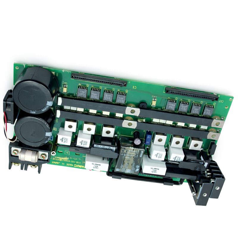
FANUC A16B-2202-0772 | Operator Panel I/O PCB — A16B-2202 Series, Series 16 / 18, Japan Origin
Part Number: A16B-2202-0772
Manufacturer: FANUC Corporation (Japan)
Product Type: Operator Panel I/O PCB
Board Series: A16B-2202
Compatible Systems: FANUC Series 16 / 18 CNC and compatible
Overview
The A16B-2202-0772 is an operator panel I/O printed circuit board from FANUC's A16B-2202 series. It belongs to the cluster of I/O boards in FANUC's Series 16 and 18 controller ecosystem that handle the communication between the CNC controller's PMC and the machine tool's operator interface hardware.
Operator panel I/O boards carry the signals that make the human-machine interface work: every button press on the machine's panel is received through this board, and every indicator lamp state driven by the PMC ladder is output through this board.
The A16B-2202 series covers a range of FANUC I/O PCBs for Series 16 and 18 applications, spanning different channel counts and I/O types.
Within this series, the individual variants are defined by their input count, output count, and electrical type — determining which machines and panel configurations they serve.
The -0772 is one such defined variant, configured for its specific operator panel I/O application within the FANUC Series 16/18 system hierarchy.
These boards are mounted within the controller cabinet and connect to the operator panel's wiring.
They receive input signals from buttons, key switches, selector switches, and emergency stop circuits, and they drive output signals to indicator lamps, audible alarms, and other panel feedback devices.
Their reliability is directly visible to the machine operator — a faulty operator panel I/O board produces missing or incorrect panel responses that are immediately apparent during machine operation.
Key Specifications
| Parameter |
Value |
| Part Number |
A16B-2202-0772 |
| Manufacturer |
FANUC Corporation |
| Product Type |
Operator Panel I/O PCB |
| Board Series |
A16B-2202 |
| Compatible Systems |
FANUC Series 16 / 18 CNC and compatible |
| Application |
Operator panel digital I/O interface |
| Origin |
Japan |
| Operating Temperature |
0 – 55°C |
| Storage Temperature |
−20 – 60°C |
| Humidity |
75% RH max (non-condensing) |
| Condition Available |
New (surplus) / Refurbished / Repaired |
The Operator Panel Interface — What This Board Does
The operator panel of a CNC machine tool is the point where the human operator interacts with the machine.
From the panel, the operator starts and stops programs, selects operating modes, enables axis movement, controls spindle and coolant functions, and acknowledges alarms.
Every one of these interactions requires a physical electrical signal path from the panel hardware to the CNC controller.
The A16B-2202-0772 provides that signal path on the input side: when the operator presses a button, the panel switch closes a circuit. The I/O PCB detects this closure and presents it to the PMC as a logical input state.
The PMC ladder program reads this state and responds — perhaps enabling a mode, initiating a function, or passing a signal to the NC kernel.
On the output side, the PMC drives indicator states: the mode is now active, the spindle is running, the tool changer is ready.
The I/O PCB takes these logical output states from the PMC and drives current through the indicator lamp circuits or relay coils connected to its output terminals.
Every panel button and every panel indicator on the machine runs through this logic path.
The I/O PCB is the hardware that makes it possible.
Source and Sink Conventions
Operator panel I/O PCBs in the A16B-2202 series are produced in source-type and sink-type electrical configurations. The two types define the direction of current flow in the output driver circuits.
Source-type outputs supply current from the board to the load. The board acts as the current source.
The load — a lamp or relay coil — connects between the board's output terminal and ground. When the PMC activates the output, the board drives current through the load.
Sink-type outputs provide a current path to ground. The board acts as the current sink.
The load connects between the supply voltage and the board's output terminal. When the PMC activates the output, the board pulls the output terminal toward ground, completing the circuit.
The type of the installed board must match the panel wiring. Installing a source-type board where a sink-type board is expected — or vice versa — produces incorrect or absent panel output function. Always confirm the electrical type of the installed board from its label before sourcing a replacement.
Fault Symptoms and Diagnosis
When an A16B-2202-0772 board develops a fault, the symptoms are visible at the operator panel. Inputs that no longer register — button presses that produce no CNC response — or outputs that are permanently on or permanently off point to a board fault or a field wiring issue.
The CNC's PMC diagnostic screen provides the direct diagnostic tool. Monitoring the input register while physically operating each switch confirms whether the board is receiving and transmitting the signal.
If the PMC shows the correct input state when the switch is operated, the board is functioning for that channel.
If the PMC shows no change while the switch is operated and the switch and wiring are confirmed good, the board's input circuit for that channel has failed.
Output faults are similarly diagnosed by using the PMC's forced-output function to command a specific output state and confirming at the panel whether the corresponding lamp or device responds.
FAQ
Q1: Several operator panel buttons stopped working after a maintenance procedure in the controller cabinet. The wiring appears intact. Could the A16B-2202-0772 be at fault?
Maintenance work in the controller cabinet can cause unintended connector disturbance. Before concluding the board is faulty, confirm all connectors between the panel wiring and the I/O PCB are fully seated.
A partially unseated connector produces exactly the pattern you describe — multiple inputs failing together.
Re-seat all connectors, test the panel function, and if the fault persists with confirmed connector seating, examine the board for damage.
Q2: Panel indicator lamps are all permanently lit regardless of PMC state. Is this an I/O PCB fault or a wiring fault?
Permanently lit outputs despite correct PMC state point to a short-circuit condition in the output driver circuit or in the wiring.
Check whether the lamp circuit common supply voltage is at its correct level — an overvoltage on the supply can cause lamps to illuminate through degraded output driver protection circuits.
If the supply voltage is correct, monitor the PMC output register to confirm the PMC is commanding the outputs off.
If the PMC command is off but the lamps remain on, the board's output driver section has likely failed.
Q3: The machine was flooded with coolant and the operator panel stopped functioning. Can the A16B-2202-0772 be recovered after coolant contamination?
Recovery depends on the extent of contamination and how quickly it is addressed. A board exposed to coolant mist that has not yet caused corrosion can often be cleaned with electronics-safe contact cleaner and returned to service after thorough drying.
A board that has been submerged or left wet for an extended period typically shows trace corrosion that cannot be fully recovered.
Inspect under magnification after cleaning — active corrosion on copper traces or component leads is a sign that the board is not reliably recoverable.
Q4: How do I confirm the I/O type (source or sink) of my installed A16B-2202-0772 before sourcing a replacement?
Read the board label directly. The label on the installed board will identify the I/O type in its description or specification line.
If the label is damaged, consult the machine's electrical documentation — the I/O PCB type is specified in the controller configuration section of the machine's maintenance manual.
If neither is available, a qualified FANUC technician can determine the type by measuring the circuit characteristics at the board's output terminals with appropriate test equipment.
Q5: After replacing this board, the CNC shows an operator panel communication error that did not exist before. What could be wrong?
An operator panel communication error after a board replacement typically indicates one of three issues: the replacement board has a different I/O Link address configuration than the original, a connector is not fully engaged on the replacement board, or the replacement board has a fault that is generating an error condition on the I/O Link bus.
Check the I/O Link address settings and connector seating first.
If both are confirmed correct, the replacement board may need to be exchanged.

 Your message must be between 20-3,000 characters!