FANUC A16B-2202-0773 | Operator Panel I/O PCB — A16B-2202 Series, Japan Origin
Part Number: A16B-2202-0773
Manufacturer: FANUC Corporation (Japan)
Product Type: Operator Panel I/O PCB
Board Series: A16B-2202
Compatible Systems: FANUC CNC control systems
Overview
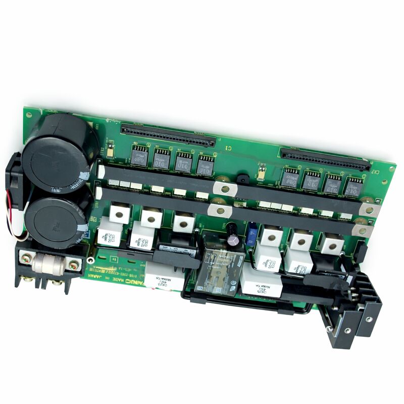
The A16B-2202-0773 is an operator panel I/O printed circuit board from FANUC's A16B-2202 series. It handles the signal interface between the CNC controller and the machine's operator panel — the front panel the machinist uses to control the machine.
Every button, switch, rotary selector, and indicator on the operator panel connects to the controller through the I/O signal paths this board manages.
The A16B-2202 series covers operator panel I/O boards across multiple FANUC CNC controller generations.
These boards translate the physical inputs from the operator panel — keypad presses, mode selection switches, cycle start, feed hold, emergency stop — into digital signals the CNC controller can act on.
They also drive the panel's output indicators: the lights that tell the operator which mode is active, which functions are enabled, and what the machine's current state is.
Without a functioning operator panel I/O board, the CNC has no reliable path for operator commands.
Axis motion may still be possible through direct parameter methods, but normal machine operation through the operator panel is not.
This board is a functional requirement for routine machining operations.
Key Specifications
| Parameter |
Value |
| Part Number |
A16B-2202-0773 |
| Manufacturer |
FANUC Corporation |
| Product Type |
Operator Panel I/O PCB |
| Board Series |
A16B-2202 |
| I/O Type |
Source type (current-sinking signal logic) |
| Compatible Systems |
FANUC CNC control systems |
| Application |
Operator panel button, switch, indicator interface |
| Origin |
Japan |
| Operating Temperature |
0 – 55°C |
| Storage Temperature |
−20 – 60°C |
| Humidity |
75% RH max (non-condensing) |
| Condition Available |
New / Refurbished / Repaired |
Operator Panel I/O — The Signal Path
When a machinist presses "Cycle Start," that physical button closure produces a voltage or ground signal that travels through a cable to the operator panel I/O board.
The board's input circuitry reads this signal and reports the state to the CNC controller's PMC ladder logic.
The PMC reads the "Cycle Start" input and, if all conditions are met, initiates the cutting cycle.
This path exists for every button and switch on the panel. Mode selector switches, feed override potentiometers, jog direction keys, spindle speed override, tool change requests — each produces a signal that the I/O board interfaces to the CNC.
On the output side, the board receives commands from the CNC — "turn on the Cycle Active lamp," "enable the Feed Hold indicator" — and drives the corresponding panel lights.
The "source type" designation describes the signal logic convention.
In source-type I/O, the board's input circuits detect current flowing from the field device.
This is one of two common industrial I/O conventions, and it determines how the panel wiring is configured.
Field devices must match the board's I/O type to operate correctly.
A16B-2202 Series — Operator Panel Boards for CNC Systems
The A16B-2202 series spans a range of operator panel I/O board variants, each with specific I/O point counts, signal logic types, and functional features matched to different controller platform configurations.
The series covers standard panel I/O in various channel counts — 48, 64, 72, 96, 104 input and output combinations — and includes variants with features such as high-speed skip inputs for probing cycles.
The -0773 variant occupies a specific position in this family, defining the particular I/O count and features appropriate for its target system configuration.
As with other operator panel I/O boards in this series, the -0773 installs in the operator panel rack and communicates with the CNC controller through the panel I/O interface.
Identifying the correct variant is essential.
Different A16B-2202 suffix numbers are not interchangeable. An incorrect board may have the same physical size and connector arrangement but different signal capacity. Always confirm the installed board's suffix from its label before sourcing a replacement.
Fault Identification — Operator Panel I/O Faults
When an operator panel I/O board fails, the failure typically presents as one of three patterns. Complete board failure makes all panel functions unresponsive — buttons do nothing, indicators all extinguish or all illuminate.
Partial failure makes specific panel functions unresponsive while others work normally — this often points to a specific section of the board's I/O array or a specific power rail on the board.
Intermittent failures — panel functions that work sometimes and not others — often originate in connector contact issues rather than the board itself.
Before concluding the board has failed, check the panel cable connections at both the board end and the panel end.
Operator panel cables accumulate wear at the connector points from repeated panel assembly and removal.
A partially seated connector or damaged contact produces the same symptom as a board failure.
If the connections are confirmed good and the fault persists, the board is the replacement candidate.
FAQ
Q1: Several specific panel keys stopped responding. Others work normally. Is the A16B-2202-0773 the fault?
Selective key failure — specific keys unresponsive while others work — can indicate a board fault, but is equally consistent with a panel keysheet fault or a panel cable fault.
Test by substituting the panel cable first if possible.
If the panel cable is confirmed good, the fault is either in the specific I/O section of the board or in the keysheet contacts for those specific keys. Inspect the keysheet under the affected keys for contamination or wear.
Q2: The machine shows an operator panel alarm after a power surge. The board has visible discoloration near one connector. What should be done?
Visible discoloration indicates a component failure from the power event. Do not attempt to restore operation with a damaged board — the fault may cascade to the CNC main board through the interface if the damaged circuit applies incorrect signals.
Replace the board. Also check the panel power supply voltage before installing the replacement to confirm the overvoltage condition is cleared.
Q3: What is the difference between source-type and sink-type operator panel I/O boards?
Source-type boards supply current from the board to the field device. The field device (button, switch) connects the current path to ground to activate the input. Sink-type boards sink current from the field device.
The field device provides voltage to the board's input. Panel wiring is different for each type — a source-type board cannot operate correctly with field wiring configured for sink-type.
Always confirm the wiring convention before sourcing a replacement board.
Q4: The machine has been retrofitted with a new operator panel. The panel does not communicate correctly with the CNC. Could the A16B-2202-0773 need replacement?
In a retrofit scenario, the panel wiring and the board's I/O convention must match. If the retrofit panel uses a different I/O convention (source vs. sink) or a different signal level, the board may need to be changed to a compatible variant.
Also confirm that the panel cable pinout matches the board's connector assignment.
A mis-wired panel will appear as a board fault but the board is not at fault.
Q5: Can component-level repair be performed on this board?
Component-level repair is possible for specific failures — damaged input protection diodes, failed indicator driver ICs, oxidised connector contacts.
Proprietary FANUC interface ICs, if damaged, are generally not independently available and make component-level repair impractical for those faults.
A qualified FANUC repair service can assess the specific failure mode and advise on repairability.

 Your message must be between 20-3,000 characters!