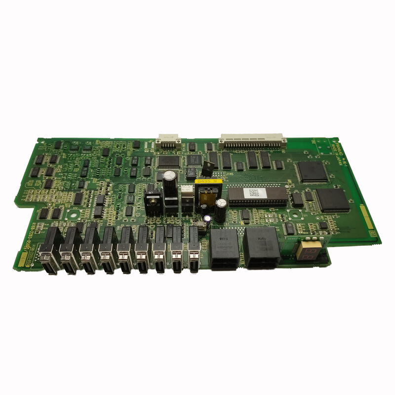
FANUC A16B-2203-0090 | Robo Monitor PCB — A16B-2203 Series, System Monitoring and Control Board for FANUC CNC and Robotic Controllers, Series 16/18/21, Japan Origin
Overview
The FANUC A16B-2203-0090 carries the "ROBO" designation — a marker within FANUC's PCB nomenclature that identifies boards associated with FANUC's robot control and robot-CNC integration product line.
The A16B-2203 series spans a range of specialised control and interface boards: power supply boards for robot controllers (A16B-2203-0370 for R-J3iB, A16B-2203-0910 for R-30iA/R-30iB), axis control and I/O expansion boards, DeviceNet interface boards (A16B-2203-0190), and monitoring/control boards like the A16B-2203-0090. Each board in the series serves a specific function within the larger control system architecture.
The ROBO monitor PCB's role is distinct from the main CPU board's role.
Where the main CPU executes the CNC or robot programme, manages servo control, and runs the PMC ladder, the monitor board handles system-level observation and control functions — the layer of electronics responsible for knowing that the system is operating within its expected parameters, communicating status to connected modules and external monitoring systems, and flagging conditions that require maintenance intervention before they become machine-stopping faults.
In robotic and robot-linked CNC applications, system status monitoring takes on particular importance because the consequences of an undetected fault can propagate rapidly through a coordinated robot-machine cell.
A robot continuing to operate with a degraded safety circuit or a CNC continuing to run with a failed position monitoring function can cause tooling damage, part scrap, or — in severe cases — safety incidents.
The monitor PCB is part of the system's safety-relevant detection layer, which is why its failure typically generates alarms that halt operation rather than allowing the system to continue in a degraded state.
Key Specifications
| Parameter |
Value |
| Series |
A16B-2203 |
| Function |
ROBO monitor / system control PCB |
| Application |
CNC + robot control integration |
| Indicators |
Multiple LED status indicators |
| Interface |
Multiple board-level connectors |
| Status |
Discontinued by manufacturer |
| Origin |
Japan |
The A16B-2203 Series — Understanding the Family
The A16B-2203 board series is one of the most functionally diverse board families in FANUC's parts catalogue. The -2203 prefix identifies boards from a common era and physical standard in FANUC's PCB architecture — typically the Series 16/18 through early i-series generation — but the last four digits distinguish widely different functions:
-0090 (this board): ROBO monitor PCB — system monitoring and control, robot-linked CNC applications.
-0110: Servo add-on or interface module — servo control extension.
-0190: DeviceNet I/F PCB — fieldbus communication interface for robot controllers.
-0200: PLC Interface PCB — machine I/O and PLC integration.
-0291: Graphic control PCB — display processing for Series 15/150 CNC.
-0370: Power supply unit — for R-J3iB robot controllers.
-0910: Power supply unit — for R-30iA/R-30iB robot controllers.
This diversity means that a part number in the A16B-2203 series tells you the board is from a specific FANUC hardware generation but says little about its function without looking at the last four digits.
When sourcing a replacement A16B-2203-0090, it is essential to use the exact part number — other A16B-2203 variants with superficially similar numbers are entirely different boards with different functions, different connectors, and different installation requirements.
LED Indicators — Diagnostic Value on the Board Face
One of the A16B-2203-0090's most practically useful features is its array of LED status indicators.
In FANUC's control system architecture, diagnostic LEDs on individual boards serve as the first line of maintenance intelligence — before connecting any test equipment or accessing the CNC's software diagnostic screens, a maintenance engineer can observe the LED states on individual boards to determine which part of the system is healthy and which has a fault.
The ROBO monitor PCB's LEDs typically indicate:
Power status: Confirming that the board's internal power supply rails (+5V, ±15V) are within specification. A dark power LED when the system is energised indicates a board-level power fault — failed voltage regulator, blown protection fuse, or damaged power trace.
Communication status: Indicating the health of the board's data link to other modules. A flashing or off communication LED when the system is in operation indicates a bus communication fault — which may be on this board, on the receiving module, or in the backplane connecting them.
Alarm status: One or more LEDs that illuminate when the board has detected an error condition in the circuits it monitors. The specific alarm pattern — which LED, steady or flashing — correlates to specific fault codes described in the CNC or robot controller's maintenance manual.
These LED states, combined with the alarm codes displayed on the CNC's operator panel, allow an experienced maintenance engineer to localise a fault to a specific board or circuit before any module is removed or replaced.
Diagnosing Failures Attributed to the A16B-2203-0090
When the ROBO monitor PCB fails, the system typically generates alarm codes in categories that relate to system status monitoring, inter-module communication, or specific safety monitoring circuits.
The challenge in diagnosis is that these alarm categories can also be generated by faults elsewhere in the system — a failed connection, a bad backplane contact, or a power supply problem can mimic a monitor board failure.
The systematic diagnostic approach is: first confirm the power supply voltages are correct at the board's connectors; then confirm all connector mating is secure and all cables are properly seated.
If power and connections are confirmed correct and the alarm persists, swap the A16B-2203-0090 with a known-good board (if available) to confirm the fault moves with the board. If the fault moves, the board is confirmed faulty.
If the fault remains, the issue is elsewhere in the system.
FAQ
Q1: What alarm codes on the CNC or robot controller specifically indicate that the A16B-2203-0090 has failed?
The specific alarm codes depend on the CNC or robot controller generation the board is installed in.
In FANUC Series 16/18 CNC systems, system-level alarms in the 900-series (DRAM parity, SRAM parity, system error) or specific monitor-related alarms in the 300-400 series may be associated with monitor board failures.
The robot controller (R-J2 or R-J3 generation) generates SRVO (servo) or SYST (system) category alarms for monitor circuit faults.
Consult the maintenance manual for the specific controller generation to identify the alarm codes associated with monitor board faults, and cross-reference against the LED states on the board itself.
Q2: Can the A16B-2203-0090 be repaired, or is replacement the only option?
Component-level repair is possible in principle — the board is not irreparably complex — but the practical feasibility depends on the failure mode. If the failure is a failed discrete component (voltage regulator, logic IC, passive component) that can be identified and replaced with appropriate SMD rework equipment, repair is feasible.
If the failure involves damage to the board's multi-layer internal traces (from a surge event or physical damage), repair becomes impractical. Most specialist FANUC repair centres offer testing and, where feasible, repair of A16B-2203 series boards.
Exchange services (receiving a refurbished tested unit in return for the failed board) are the most common service path for this part.
Q3: Is the A16B-2203-0090 used in CNC-only machines, or only in robot-linked applications?
The "ROBO" designation indicates the board's primary application context — FANUC's robot controller and robot-CNC integration product line.
However, some FANUC CNC systems that include robot coordination functions (such as multi-axis CNC systems with integrated robot axis control) also use boards from the ROBO family.
The definitive answer for any specific machine is in that machine's parts list or hardware connection manual — if the A16B-2203-0090 is listed as part of that machine's configuration, it is the correct board regardless of whether the machine is a pure CNC, a robot, or a hybrid system.
Q4: How many LED indicators are on the A16B-2203-0090, and what is their diagnostic significance?
The exact number and labelling of LED indicators varies by board revision, but A16B-2203 series monitor boards typically carry between 4 and 12 LEDs covering power status, communication link status, and fault indication.
The LED positions and their meanings are documented in the controller's maintenance manual appendix that describes the PCB's physical layout.
The most immediately useful LEDs are the power-good indicators — if any power LED is off when the system is energised, no software diagnosis is needed; the fault is in the board's power circuitry.
Q5: The system works normally when cold but generates monitor board alarms after warming up. What does this suggest?
Temperature-dependent faults that appear after warm-up and clear when the system cools down point to a thermally marginal component on the board — typically an electrolytic capacitor with increased ESR at operating temperature, a semiconductor junction that becomes leaky when hot, or a solder joint with a micro-crack that opens under thermal expansion and closes when cool.
This failure mode is characteristic of an aged or ESD-stressed board approaching end of reliable life.
The temporary workaround (allowing the system to cool before restarting) is not a maintenance solution — the board should be replaced before the thermally-induced fault becomes permanent and causes unplanned downtime in production.

 Your message must be between 20-3,000 characters!