FANUC A16B-2203-0661 | Power Supply PCB — A16B-2203 Series, CNC and Robot Controller Power Board, Industrial Automation Spare, Japan Origin
Overview
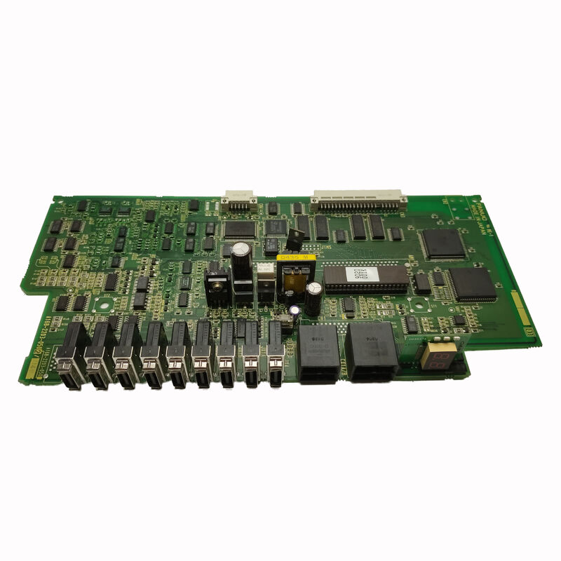
The FANUC A16B-2203-0661 is a power supply PCB from FANUC's A16B-2203 board family — a series that spans both functional control boards (monitor PCBs, axis expansion boards, communication interfaces) and power supply boards for FANUC's CNC and robot controller product line.
The power supply board occupies a foundational role in the controller's electrical architecture: every other board in the system — the CPU, the servo interface, the I/O boards, the operator panel connections — depends on the power supply to provide stable, correctly regulated DC voltages within specified tolerances.
FANUC's controller power supply designs convert the incoming AC supply (typically 200–240VAC in the machines where FANUC controllers are most commonly found) through a regulated switching converter topology to produce the multiple DC voltage rails required by the system's electronics.
The switching converter approach — rather than the older linear regulator approach — provides high efficiency (the PSU generates less waste heat for a given output power), wide input voltage tolerance (the system remains stable across the full international AC supply range without manual voltage adjustment), and fast response to load transients (the converter's control loop adjusts the switching duty cycle within microseconds when a new module draws current, preventing voltage droops that could cause logic errors in the control circuits).
The A16B-2203-0661's placement within the controller — whether it is a standalone PSU board or integrated into a backplane assembly — follows the standard FANUC physical mounting practice for its generation.
Like other A16B-2203 power boards (notably the -0370 for R-J3iB and the -0910 for R-30iA/R-30iB controllers), the -0661 is designed to deliver its full rated output power continuously within the controller's thermal environment, with protection circuits that respond to overload, overvoltage, and overtemperature conditions before any damage occurs.
Key Specifications
| Parameter |
Value |
| Function |
Power supply PCB |
| Series |
A16B-2203 |
| Output Rails |
Multi-rail DC (5V, ±15V, 24V typical) |
| Input |
200–240VAC |
| Protection |
OVP, OCP, OTP |
| Origin |
Japan |
Why Power Supply Boards Fail — And Why They Matter
In the hierarchy of CNC and robot controller maintenance, the power supply board sits at the top of the criticality ranking. A failed power supply board brings the entire controller to a complete halt — no CPU execution, no servo control, no operator panel response.
Every downstream board, module, and circuit is equally affected because they all share the same power source.
This makes the power supply board both the most important board in the system (because everything else depends on it) and, in practice, one of the more frequently replaced boards because it endures conditions that accelerate component wear.
The primary wear mechanism is thermal cycling of electrolytic capacitors.
Electrolytic capacitors are the workhorses of power supply circuits — they store energy during the converter's switching cycle, filter the output voltage ripple, and maintain stable supply voltages during transient load changes.
They contain a liquid electrolyte that is essential to their capacitance and ESR (equivalent series resistance), and this electrolyte slowly evaporates over time, particularly at elevated temperatures.
As the electrolyte depletes, the capacitance decreases and the ESR increases — leading to increased output voltage ripple, degraded transient response, and eventually instability or complete failure of the regulated output.
The rate of electrolyte evaporation is strongly temperature-dependent: for every 10°C increase in operating temperature above the capacitor's rated temperature, service life approximately halves.
CNC and robot controllers installed in non-air-conditioned production environments, or in cabinet configurations with inadequate cooling airflow, may experience accelerated capacitor aging.
A power supply that provides 15–20 years of reliable service in a well-cooled, temperature-controlled environment may show symptoms of capacitor failure in 8–10 years in a hot plant environment.
Power Supply Failure Symptoms and Their Causes
Power supply failures present with characteristic symptoms that reflect the nature of the failure:
Complete loss of control power: The controller does not power up at all when the main supply is applied. All indicator lights are off, the operator panel is dark, and no cooling fans run. This indicates a complete PSU failure — typically a failed primary switching transistor, a blown primary fuse, or a catastrophic failure in the input rectifier.
Complete failure often occurs suddenly, sometimes following a power surge or in-rush event.
Unstable system with intermittent alarms: The controller runs but generates random alarms that do not correlate with any specific machine function, clears on power cycle, and recurs unpredictably.
This is the classic presentation of age-related capacitor degradation — the PSU's output voltage is within specification at light load and room temperature but droops out of specification under full module loading or at elevated cabinet temperature.
The digital logic circuits in the CNC modules are sensitive to supply voltage — even a 5% sag in the +5V rail can cause logic errors that manifest as system alarms or erratic programme execution.
Overtemperature alarm: The PSU's thermal protection circuit detects that the switching transistor or transformer is exceeding its safe temperature and shuts down the supply.
This may indicate a failed cooling fan within the cabinet, blocked ventilation paths, or — on the board itself — increased power dissipation due to degraded components that are generating more heat than normal to maintain the same output power.
One output rail failed: The controller partially powers up — some functions work, others do not.
The +5V rail might be healthy (CPU and logic operate) while the +24V rail is absent (I/O boards and relay circuits do not respond).
This selective failure points to a specific branch of the power supply circuit and is usually repairable at component level.
Preventive Maintenance for Long-Service Power Supplies
The A16B-2203-0661's service life can be extended through proactive maintenance practices:
Scheduled capacitor replacement — a full recap of the PSU's electrolytic capacitors using new components rated for the operating temperature — is the most effective preventive action. Most specialist FANUC repair centres include capacitor replacement as a standard part of PSU refurbishment, regardless of the presenting symptoms.
Performing this proactively at 10-year intervals (or sooner in hot environments) eliminates the most common failure mode before it causes unplanned production downtime.
Cabinet cooling maintenance — ensuring that the cabinet's cooling fans are operational, that air filters are clean and not restricting airflow, and that the ambient temperature in the area of the controller cabinet does not consistently exceed the CNC's rated operating temperature — is equally important.
Capacitor life is strongly temperature-dependent; every degree of reduction in the PSU's operating temperature extends capacitor service life measurably.
FAQ
Q1: The controller powers up briefly and then shuts down, with the cooling fans visible running for a second or two. Is this a PSU fault?
This symptom — brief power-up followed by immediate shutdown — is consistent with an overload protection trip. The PSU starts, delivers power to the modules, detects that the total current draw exceeds its overcurrent protection threshold, and shuts off to prevent damage.
Common causes: a shorted module (install modules one at a time to identify the faulty one), a failed capacitor in the PSU's output filter that presents as a momentary short during startup, or a genuine degradation of the PSU's current limit threshold due to aged sense resistors.
Removing all downstream modules and powering up the PSU alone (if the design allows) helps isolate whether the fault is in the PSU or in a module.
Q2: Can a bench multimeter be used to test the A16B-2203-0661 before installation?
A multimeter can verify output voltages if the board can be powered up on a bench with a dummy load that approximates the controller's real load — testing unloaded or with minimal load may show correct voltages even if the PSU cannot maintain regulation under real load conditions due to marginal capacitors.
A bench test is more informative than no test, but the definitive test is operation in the actual controller with the full module complement installed.
If a FANUC test rig is available at a repair centre, that provides the highest confidence in the board's performance before shipment.
Q3: After replacing the A16B-2203-0661, should any parameters or settings be reconfigured in the CNC?
The power supply board itself contains no programmable data or settings — it has no memory and no user-configurable registers. Replacing it requires no parameter changes in the CNC. However, if the PSU failure was severe enough to cause an uncontrolled voltage event on the CNC's power rails before the protection circuits responded, data corruption in the SRAM modules (parameter and programme storage) is possible.
After any PSU replacement following a hard failure, verify that all CNC parameters are intact by checking critical values against the last known-good backup before returning the machine to production.
Q4: How is the correct replacement PSU voltage rating confirmed for the A16B-2203-0661?
The PSU is designed for the standard FANUC controller input voltage range — typically 200–240VAC, which covers the international industrial supply voltage range.
The A16B-2203-0661 is a fixed-configuration board and does not require voltage range selection or jumper settings for different supply voltages within the supported range.
The board's input voltage specification is confirmed from FANUC's product documentation or from the original board's label.
The CNC's power supply connection diagram in the machine's electrical documentation also identifies the input voltage specification.
Q5: Is the A16B-2203-0661 repairable if it has failed due to a capacitor issue rather than a catastrophic component failure?
Yes. Capacitor failure is one of the most tractable repair scenarios for a PSU board — the failed capacitors are identifiable through visual inspection (bulged or leaking tops), ESR measurement with an appropriate tester, or simply by scheduled replacement based on age.
Specialist FANUC repair centres routinely perform this repair using capacitors matched to the original's voltage rating, capacitance, temperature rating, and physical dimensions.
A fully recapped and tested A16B-2203-0661 from a competent repair centre represents an effective and cost-efficient alternative to sourcing a new or surplus board at full market price.

 Your message must be between 20-3,000 characters!