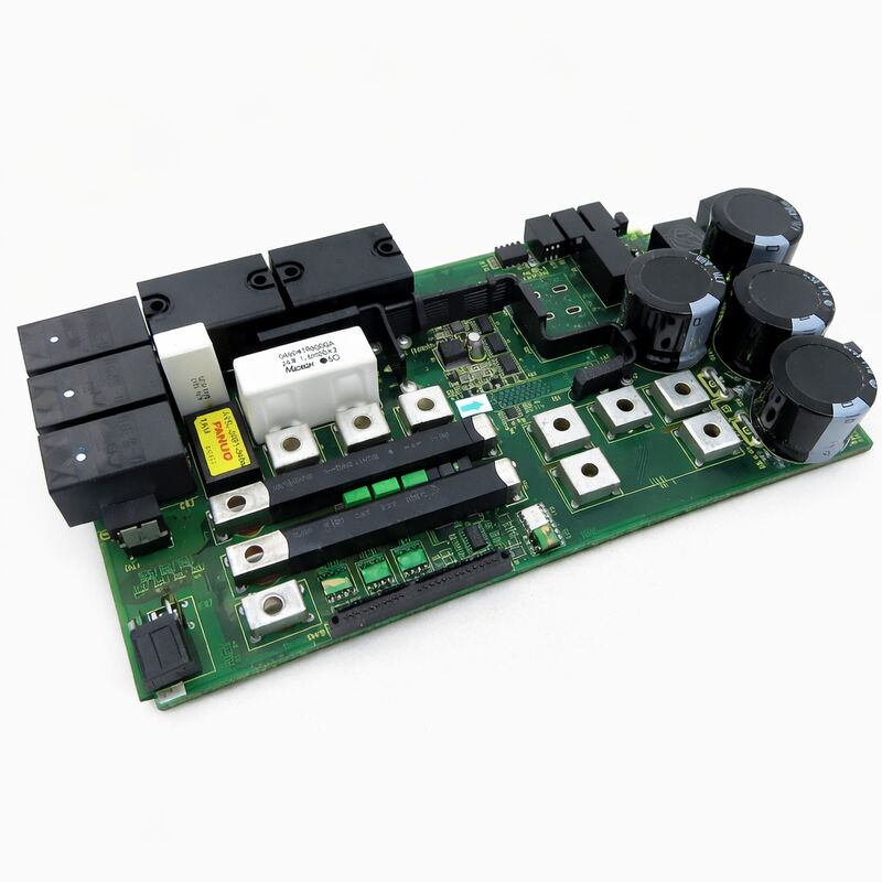
FANUC A16B-3200-0500 | I/O PCB — Series 0i-B CNC, Japan Origin
Part Number: A16B-3200-0500
Manufacturer: FANUC Corporation (Japan)
Product Type: I/O PCB
Board Series: A16B-3200
Compatible Systems: FANUC Series 0i-B CNC controllers
Application: I/O interface and data communication
Overview
The A16B-3200-0500 is the I/O printed circuit board commonly used in FANUC's Series 0i-B CNC controller. The 0i-B — the second generation of FANUC's compact 0i CNC family — was widely adopted in turning centres and machining centres across its production era.
The I/O PCB is the board responsible for the digital input and output interface between the CNC controller and the machine tool's field wiring.
Every sensor reading and every relay output from the PMC ladder program passes through this board on its way between the controller's logic and the physical machine.
The 0i-B was designed for cost-effective, full-featured CNC performance in a compact package.
It brought FANUC's i-series capability to machines where the full-sized 16i or 18i would be over-specified.
The I/O PCB in this architecture performs the same field interface function as the I/O PCBs in larger FANUC systems, scaled to the 0i-B's I/O requirements.
The A16B-3200-0500 is the board that performs this function.
In the 0i-B controller's modular structure, the I/O PCB sits alongside the main CPU board and the power supply.
It routes the digital input signals from the machine — limit switches, proximity sensors, pressure switches, operator panel buttons — to the PMC's input register.
It drives the output signals from the PMC — solenoid valves, relay coils, spindle enable, coolant pump control — out to the machine hardware.
This bidirectional field interface is the I/O PCB's core purpose.
Key Specifications
| Parameter |
Value |
| Part Number |
A16B-3200-0500 |
| Manufacturer |
FANUC Corporation |
| Product Type |
I/O PCB |
| Board Series |
A16B-3200 |
| Compatible Systems |
FANUC Series 0i-B CNC (0i-TB, 0i-MB and compatible) |
| Application |
Digital I/O interface for machine tool field wiring |
| Origin |
Japan |
| Operating Temperature |
0 – 55°C |
| Storage Temperature |
−20 – 60°C |
| Humidity |
75% RH max (non-condensing) |
| Condition Available |
New (surplus) / Refurbished / Repaired |
I/O Architecture in the 0i-B System
The 0i-B controller uses I/O Link — FANUC's serial communication protocol for connecting I/O devices to the CNC.
The I/O PCB in the 0i-B participates in the I/O Link network. Signals from the machine's wiring arrive at the I/O PCB's connectors, are digitised, and then transmitted over I/O Link to the PMC. Output commands from the PMC travel back over I/O Link to the I/O PCB, which drives the appropriate output circuit.
This serial link architecture means the physical distance between the CNC controller and the I/O PCB installation point is not limited by the length of individual signal wires.
The I/O Link cable carries all channel data between the controller and the I/O hardware — a significant practical advantage in machine tool installations where the CNC cabinet and the machine control panel may be separated by a distance that would make individual wire runs impractical.
The I/O PCB processes the raw field signals — debouncing inputs, protecting against transient noise, managing output short-circuit conditions.
This signal conditioning means the PMC receives clean, reliable digital representations of the machine's actual state rather than raw signals subject to the noise and switching transients of an active industrial environment.
0i-B System Context
The 0i-B controller generation — spanning 0i-TB for turning and 0i-MB for milling — fitted the mainstream of the machine tool market during its production era. FANUC equipped it with the PMC-SB7 ladder engine (on the -0491 main board variant), FSSB servo communication, and the I/O Link field interface provided through this board.
Together, these defined a complete, modern CNC system.
Machines built on the 0i-B platform remain in active production service globally. Maintenance parts for these machines are in consistent demand.
The A16B-3200-0500 I/O PCB, as one of the field-replaceable boards in the 0i-B stack, is sourced when an I/O-related fault traces back to the board rather than to field wiring or to the connected I/O devices.
Fault Isolation — Board or Wiring?
I/O faults in CNC systems are among the most common maintenance issues, but not all I/O faults trace back to the I/O PCB. The first step in any I/O fault investigation is to confirm which element has failed: the field device, the wiring, or the PCB.
The CNC's PMC diagnostic screens show the live state of every I/O channel. If a channel reads incorrectly, monitor it while physically actuating the field device or measuring the wiring signal.
A channel that reads incorrectly when the wiring signal is confirmed correct at the board's connector points to the board.
A channel that reads correctly only when the field signal is above a certain threshold may indicate a degraded input circuit on the board.
Multiple I/O channels failing together — especially channels in the same connector group — points more strongly to a board fault than to a field wiring issue, which typically affects one signal path at a time.
FAQ
Q1: Several inputs stopped reading correctly after a power surge in the machine room. The wiring tests as good. Is the A16B-3200-0500 likely damaged?
Power surges commonly damage I/O PCB input circuits because the inputs connect directly to field wiring where surge energy propagates.
Protection components on the board absorb surge energy, but repeated events or a severe surge can damage the input circuits beyond the protection stage.
With wiring confirmed good, the board is the next element to investigate.
Check whether the affected inputs are all in one connector group — grouped failures often confirm board damage.
Q2: The 0i-B machine PMC shows an alarm but all field wiring tests normal. The I/O PCB has no visible damage. Could the board be at fault without visible signs?
Yes. Many I/O PCB failures — degraded optocouplers, failing output driver ICs, high-resistance ground connections — produce no visible physical indication.
A board that looks intact can still have failed internal components.
If wiring and field devices are confirmed good, the I/O PCB should be replaced as the next diagnostic step. Install the replacement and confirm the alarm clears before concluding the diagnosis.
Q3: Can the A16B-3200-0500 from an 0i-TB machine be used in an 0i-MB machine?
The I/O PCB hardware serves the same function in both 0i-TB (turning) and 0i-MB (milling) configurations.
The board itself does not differentiate between machine types — it provides field I/O connection for whichever PMC ladder is loaded in the controller.
Confirm the board revision and I/O Link configuration are compatible.
If the part number and revision match, the board is interchangeable between 0i-TB and 0i-MB installations.
Q4: After replacing the I/O PCB, some outputs work but others do not. The PMC program appears correct. What should be checked?
Non-functioning outputs after board replacement with a correct PMC program point to output address assignment.
Confirm the PMC's Y-address map matches the I/O PCB's connector assignment for the affected outputs.
Also verify that any output configuration parameters in the CNC that specify output channel assignments are set correctly.
If address assignment is confirmed, test the non-functioning output channels directly with the PMC's forced output function to confirm whether the hardware is responding.
Q5: The I/O PCB was replaced. Now the machine powers on but the I/O Link fails to establish. What does this indicate?
An I/O Link failure after a board replacement indicates either an I/O Link configuration mismatch between the new board and the controller, a faulty I/O Link cable connection, or a board fault on the replacement.
Check the I/O Link cable between the main CPU board and the I/O PCB — confirm both ends are securely connected.
Also confirm the I/O Link slot configuration in the CNC parameters matches the new board's I/O Link address.
If both are confirmed correct, the replacement board may itself be faulty.

 Your message must be between 20-3,000 characters!