FANUC A16B-3200-0513 | A16B-3200 Series Power PCB — FANUC CNC Industrial Automation, Japan Origin
Part Number: A16B-3200-0513
Manufacturer: FANUC Corporation (Japan)
Product Type: Power PCB / Power Supply Board
Board Series: A16B-3200
Application: FANUC CNC controller and industrial automation systems
Overview
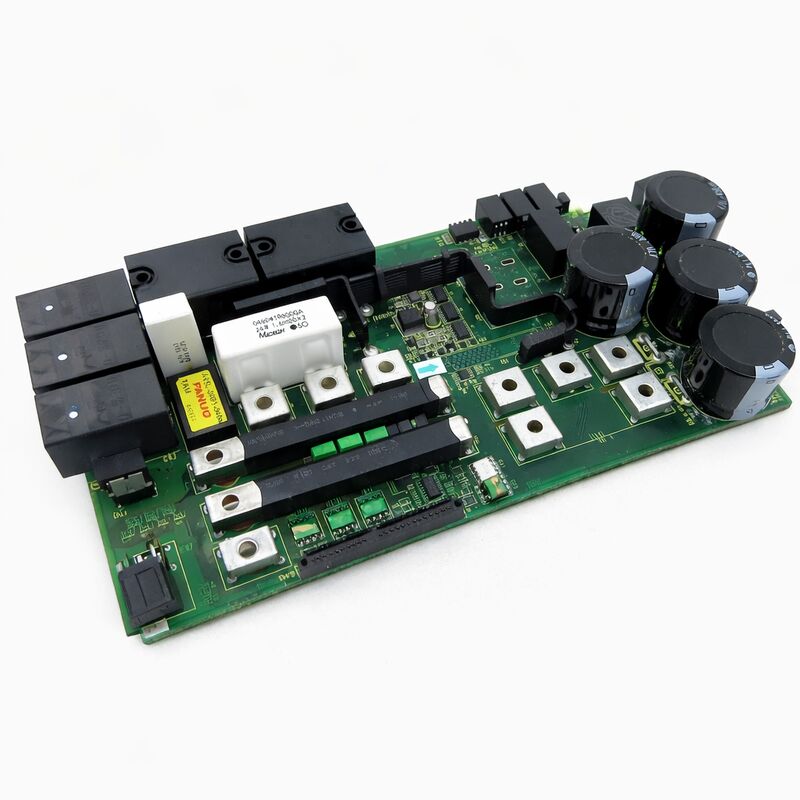
The A16B-3200-0513 is a power printed circuit board from FANUC's A16B-3200 series — the family of controller boards that underpins FANUC's CNC and industrial automation platforms across multiple generations of machine tools, robots, and production systems.
Power boards in this series are responsible for generating and distributing the regulated DC voltages that every other board in the controller depends on.
When the power board functions correctly, it is invisible — the system starts, operates, and stops without incident. When it fails, the consequences are immediate.
No power board means no controller operation, period.
FANUC's A16B-3200 series spans a broad range of functional board types: main CPU boards, I/O boards, servo interface cards, and power supply boards.
The power supply board occupies a dedicated slot position in the controller rack, converting the incoming supply into the precise voltage rails that serve the controller's logic, memory, display, and communication circuits.
Tolerances are tight. FANUC's industrial-grade controller design specifies voltage rails that are regulated closely enough to ensure stable operation across the full range of ambient temperatures and load conditions the controller encounters.
The A16B-3200-0513 serves its specific controller platform within the A16B-3200 family.
It provides the power infrastructure that all other boards in that controller depend on, making it one of the most foundational components in the system's hardware stack.
Key Specifications
| Parameter |
Value |
| Part Number |
A16B-3200-0513 |
| Manufacturer |
FANUC Corporation |
| Product Type |
Power PCB / Power Supply Board |
| Board Series |
A16B-3200 |
| Application |
FANUC CNC controller systems |
| Origin |
Japan |
| Operating Temperature |
0 – 55°C |
| Storage Temperature |
−20 – 60°C |
| Humidity |
Non-condensing, ≤75% RH |
| Condition Available |
New (surplus) / Refurbished / Repaired |
Power Distribution in FANUC CNC Controller Architecture
The FANUC CNC controller is a rack-mounted assembly of functionally distinct boards. Each board performs a specific role: the main CPU runs the operating software; the PMC board executes the machine ladder logic; servo interface cards communicate with the drive amplifiers; memory modules store the parameter and program data.
All of these boards need stable, regulated DC power to operate. The power PCB is what provides it.
In the A16B-3200 controller architecture, the power board receives the incoming supply — typically from the machine's main power cabinet — and conditions it through switching regulators, linear post-regulators, and filtering stages into the multiple voltage rails that the controller's backplane distributes.
Each rail has a defined voltage and a current capacity matched to the loads it serves.
The power board also includes protection circuitry: overvoltage protection that disconnects the rail before excess voltage can damage downstream boards, overcurrent protection that prevents a short circuit on one rail from cascading into others, and soft-start circuitry that ramps up the supply voltages in a controlled sequence at power-on.
The LED indicators on the power board's front face — visible through the controller's front panel or directly on the board — provide first-level diagnostics.
A supply rail that is out of tolerance illuminates the corresponding LED. This rapid visual feedback is often the starting point for diagnosing whether a controller fault originates in the power board or elsewhere.
Power Board Faults and Their Symptoms
Power board failures produce recognisable symptom patterns that distinguish them from other controller board faults.
The most complete failure mode — where the power board delivers nothing — results in a dark controller: no display, no LED activity, no fan operation. The machine is completely inert.
Partial failures are more common and more diagnostic.
A single rail that has drifted low or failed causes the boards powered by that rail to malfunction while boards on other rails operate normally.
The controller may partially initialise, showing some activity on the display, then halt with an alarm at the point in its startup sequence where it first calls on the failing rail.
Tracing the alarm to the startup stage and then to the rail that stage depends on is a reliable way to confirm the power board as the fault source.
Age-related degradation is the dominant failure mechanism for power boards in long-service controllers. Electrolytic capacitors in the switching regulator and output filter stages lose capacitance and gain ESR over years of operation at elevated temperatures.
The affected supply rail develops ripple that eventually exceeds the downstream boards' input tolerance. Before complete failure, the symptom is intermittent — unexplained resets, parameter corruption, or erratic behaviour that is temperature-dependent and worsens as the controller warms up in operation.
Legacy Parts Availability
FANUC's A16B-3200 series boards from earlier controller generations are no longer in production.
The aftermarket supply chain for these boards — tested surplus units from decommissioned machines, professionally refurbished boards with restored capacitors and functional testing, and repair services for specific component-level faults — is the primary source for replacement.
When sourcing a replacement A16B-3200-0513, confirm the exact part number from the board's own label.
Power boards within the A16B-3200 series that differ by suffix digit may have different voltage rail specifications, connector arrangements, or power ratings. Physical similarity is not a reliable indicator of compatibility.
FAQ
Q1: The FANUC controller powers on but shuts down after a few minutes of operation. No alarm code is displayed before shutdown. Could the A16B-3200-0513 be responsible?
Thermal shutdown after a warm-up period is a classic symptom of aging electrolytic capacitors in the power board's switching regulator stage.
As the capacitors age, their ESR increases with temperature.
When the board warms up, the ESR rise causes supply ripple to exceed the threshold that triggers the overvoltage or undervoltage protection, shutting the system down.
This symptom appearing after a period of otherwise normal operation strongly implicates the power board as the fault source.
Q2: After a power surge event, the controller does not power on at all. The incoming supply has been confirmed normal. Is the power board likely damaged?
Power surge events frequently damage power boards.
The surge voltage arrives at the power board's input terminals before the board's protection can respond.
The components most vulnerable are the input rectifier diodes, the input filter capacitors, and the primary switching transistors.
These are all located on the power board. If the incoming supply is confirmed normal and the controller shows no signs of life, the power board is the first suspect. Check any accessible fuses on the board before ordering a replacement.
Q3: One axis on the CNC shows servo alarms while the other axes are normal. All power LED indicators on the A16B-3200-0513 are green. Is the power board still possibly at fault?
A single-axis servo alarm with all power rails showing normal is unlikely to originate in the power board.
The power board supplies rails to all boards simultaneously — a failing rail would affect multiple boards, not just one axis.
Single-axis alarms point to the servo amplifier for that axis, the motor, the feedback cable, or the servo interface circuitry specific to that axis. The power board can be set aside as a likely cause in this case.
Q4: How should a spare A16B-3200-0513 be stored to preserve its functionality?
Store in original anti-static packaging. Maintain stable room temperature and low relative humidity.
Avoid temperature cycling, which stresses solder joints on the board's surface-mount components.
If the board has been in storage for more than a few years, inspect the electrolytic capacitors for visible signs of degradation — swollen tops or electrolyte leakage — before installing in a production machine.
For long-term storage, periodic reforming of the electrolytic capacitors extends their service life.
Q5: A refurbished A16B-3200-0513 is available. What should a reputable refurbishment include for a power board of this type?
A proper power board refurbishment includes replacement of all electrolytic capacitors with new components matching the original specification (or with rated capacitors at equivalent or better specs), inspection and replacement of any failed protection devices, functional testing under load with all output rails measured at rated current, and verification that the board meets the voltage accuracy and ripple specifications.
Cosmetic cleaning and inspection for any physical damage round out a complete refurbishment.

 Your message must be between 20-3,000 characters!