FANUC A16B-3200-0515 | Drive Control Circuit Board — A16B-3200 Series, Japan Origin
Part Number: A16B-3200-0515
Manufacturer: FANUC Corporation (Japan)
Product Type: Drive Control Circuit Board (PCB)
Board Series: A16B-3200
Application: FANUC CNC and drive control systems
Overview
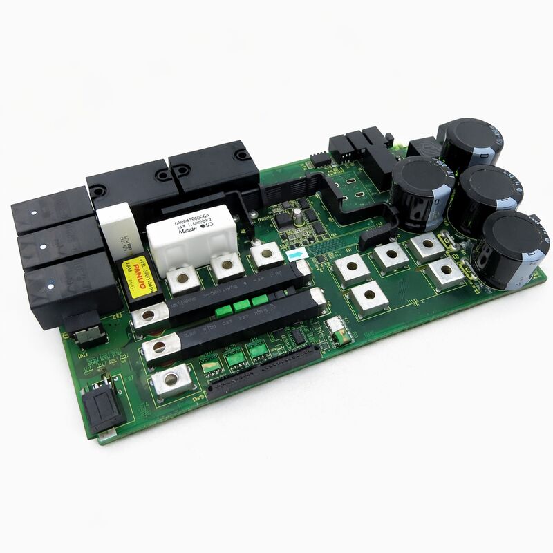
The A16B-3200-0515 is a drive control circuit board from FANUC's A16B-3200 series. The A16B-3200 series encompasses control boards used across FANUC's CNC and automation systems — from main CPU boards that run the CNC control software, to subsidiary control boards that manage specific functions within the controller or drive system. The -0515 is a drive control PCB that handles defined control functions within its installed position.
Drive control boards in FANUC systems sit between the high-level command logic — which decides what needs to happen — and the power electronics that execute those decisions.
They receive commands, process feedback, generate the control signals for the power stage, and report status back to the higher-level controller.
The precision of motion in a FANUC-controlled machine depends on this processing being executed correctly and reliably at every control cycle.
The A16B-3200-0515 is manufactured in Japan to FANUC's production standards for control electronics.
Like other A16B-3200 series boards, it is designed for the industrial environment — operating through the temperature cycling, vibration, and electrical noise that characterize active manufacturing settings.
Key Specifications
| Parameter |
Value |
| Part Number |
A16B-3200-0515 |
| Manufacturer |
FANUC Corporation |
| Product Type |
Drive Control Circuit Board |
| Board Series |
A16B-3200 |
| Application |
FANUC CNC and drive control systems |
| Origin |
Japan |
| Operating Temperature |
0 – 55°C |
| Storage Temperature |
−20 – 60°C |
| Humidity |
75% RH max (non-condensing) |
| Condition Available |
New / Refurbished / Repaired |
Drive Control PCBs in FANUC Architecture
FANUC's drive and control system design uses modular board assemblies. A drive unit — whether a servo amplifier or spindle amplifier — contains multiple PCBs that each handle a defined portion of the drive's total function.
One board handles the current sensing and gate drive logic; another handles the communication interface with the CNC; a third manages fault detection and protection.
Together these boards form the complete control section of the drive.
This modular design serves a maintenance purpose. When a drive unit develops a fault, identifying which board within the control section has failed allows targeted replacement of just the faulty board rather than the complete drive assembly.
The A16B-3200-0515 is one such replacement-level board — when its specific function within the drive or control system fails, this board is the spare that restores it.
The A16B-3200 series spans FANUC products across several generations and application types.
Boards in this series are found in CNC main controller racks, in servo and spindle drive units, and in specialized control assemblies.
Handling and Installation Safety
Control boards for drive systems require standard anti-static handling precautions.
The gate driver ICs and analog signal processing components on drive control boards are sensitive to electrostatic discharge. Ground yourself before handling the board.
Handle by the edges. Avoid contact with circuit traces, component pins, and connector contacts.
Before installing a replacement board, power down the drive completely and allow the DC bus capacitors to discharge — this typically takes at least five minutes after AC power removal.
The residual energy in drive capacitors can cause injury and can also damage the replacement board if installed while the bus is live.
After installation, confirm all connectors are fully seated before restoring power.
Partially engaged connectors are a common source of post-replacement faults that appear as board failures but are actually connection issues.
Part Number Identification
The A16B-3200 series contains many variants serving different functions. Two boards from this series may be physically similar while serving completely different functions. The full part number — including the -0515 suffix — is the only reliable identifier.
Before sourcing a replacement, confirm the exact part number from the label on the board being replaced.
Do not substitute a different A16B-3200 suffix number without confirmed compatibility information.
An incorrect variant will produce incorrect or absent control function.
FAQ
Q1: A drive unit faults with a control error code. The power transistors and capacitors test as good. Could the A16B-3200-0515 be responsible?
Control error codes with intact power components point directly to the control board section.
The drive's power stage is mechanically functional but the control electronics are reporting an error.
Identify which board in the control section generates the specific error code from the drive's fault documentation, then source the appropriate replacement.
Q2: The board was removed for inspection and shows no visible damage. Should it be reinstalled or replaced?
Visual inspection alone does not confirm electrical function. Many failure modes — internal IC failures, degraded capacitors, high-resistance solder joints — produce no visible indication.
A board that passes visual inspection but was removed due to an operational fault should be tested under power in the system before being returned to service.
Q3: After board replacement the drive powers on but the fault reappears within minutes. Was the replacement board defective?
A fault that reappears quickly after board replacement suggests either the replacement board has a similar fault, the original fault cause was not the board, or a condition in the environment — voltage spike, heat, contamination — is damaging boards.
Investigate the fault cause rather than replacing the board again without analysis.
Q4: How do I confirm the A16B-3200-0515 is the correct board for my application?
Read the part number from the installed board's label directly. The A16B-3200 series number plus the -0515 suffix together constitute the complete part number.
Cross-reference against the machine's electrical documentation or the drive unit's parts list.
The part number on the board is the definitive identifier — do not rely on dimensions or connector appearance alone.
Q5: Is component-level repair viable for the A16B-3200-0515?
Component-level repair is viable for some fault types — protection device failures, blown fuses on the board, connector damage, oxidized contacts.
Faults in proprietary FANUC ASICs or custom ICs are generally not repairable at the component level as these parts are not independently available.
A qualified FANUC drive repair specialist can evaluate the specific failure mode and advise on the practical repair path.

 Your message must be between 20-3,000 characters!