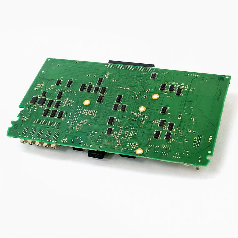
FANUC A16B-3200-0522 | i-A Stand-Alone Control Main CPU PCB — A16B-3200 Series, CNC Master Board for i-Series Stand-Alone Configuration, Japan Origin
Overview
The FANUC A16B-3200-0522 belongs to the A16B-3200 main CPU PCB family serving the i-series "A" generation of FANUC CNC controllers — the first generation to carry the "i" designation, which FANUC introduced to distinguish its high-performance, open-architecture capable controllers from the previous letter-series (A, B, C) generations.
The "i" CNC generation arrived with expanded interpolation capabilities, FSSB servo communication, integrated graphics, and a network-ready architecture that set the pattern for FANUC CNC design through the following decade.
The "stand-alone" designation in the board's official description identifies the controller's physical configuration.
In FANUC's i-series, the same CNC generation was offered in two physical configurations: the LCD-mount type, where the CNC processor boards are mounted directly behind the operator panel's LCD screen in a compact integrated unit; and the stand-alone type, where the CNC processor occupies a separate rack or enclosure connected to a separate LCD/MDI display unit.
Stand-alone configurations are used when the control unit must be mounted in a location away from the operator panel, when the required I/O count or option card count exceeds what fits behind the LCD panel, or when the machine's design places the control electronics in a cabinet separate from the operator station.
The A16B-3200-0522 is the master board in the stand-alone unit — the board that all other boards in the stand-alone rack communicate through, and that processes all CNC control functions.
Its relationship to the operator panel is via a connection cable from the stand-alone unit's display interface to the separate LCD/MDI panel, rather than a direct mechanical back-to-panel mounting.
Key Specifications
| Parameter |
Value |
| CNC Generation |
i-series Model A (i-A) |
| Configuration |
Stand-alone controller |
| Series |
A16B-3200 |
| Function |
Main CPU / master board |
| Data Required |
Parameters and programmes must be reloaded after replacement |
| Status |
Available — refurbished, tested |
| Origin |
Japan |
The i-Series A Generation — Context and Significance
The FANUC i-series "A" designation identifies the first generation of FANUC's i-series CNC platform, which appeared from the late 1990s.
The i-A generation delivered several capabilities that the previous C-series had not: FSSB optical fibre servo communication (replacing the analogue ±10V and earlier digital interfaces), higher resolution encoder processing, improved block processing rates for faster execution of complex programmes, and a display architecture that supported graphical toolpath simulation on the operator panel screen.
For maintenance engineers, the i-A generation represents a substantial installed base of machines that were built in the early-to-mid 2000s and continue to operate today.
Automotive suppliers, aerospace component manufacturers, and general precision machining companies built significant quantities of CNC lathes, machining centres, and grinding machines on i-A controllers.
These machines have well-established maintenance patterns — the boards that commonly fail after 15–20 years of service are the same ones in multiple machines, making the A16B-3200-0522 a regular demand item in the FANUC spare parts market.
The stand-alone configuration, specifically, was preferred by machine tool builders who needed the flexibility to mount the CNC control unit independently of the operator station.
This includes large floor-standing machining centres where the operator console is on a swing arm, horizontal machining centres with pallet changers where the operator panel is on a separate post, and machines where the electrical cabinet heat makes it impractical to mount the CNC processor behind the display.
Stand-Alone Configuration — Physical and Logical Architecture
In the stand-alone CNC configuration used with the A16B-3200-0522, the controller chassis contains the main CPU board, I/O boards, servo interface cards, power supply, and any option boards in a rack structure. This rack is physically separate from the operator's LCD/MDI display unit.
A cable bundle connects the two units — carrying display data to the screen and MDI keystrokes from the keyboard back to the controller.
The A16B-3200-0522 serves as the rack's master: it executes the CNC software, manages the servo loops via FSSB, runs the PMC ladder, and drives the display data to the remote LCD panel.
The stand-alone chassis design allows more option slots than the LCD-mount configuration — this matters for machines that need multiple I/O boards, additional communication cards (Ethernet, serial), or expanded servo capacity that would overflow the space behind an LCD panel.
When replacing the A16B-3200-0522, the replacement board must match the software version and hardware revision installed in the specific machine. Within the i-A generation, different software versions support different CNC series (16i-A for multi-axis machining centres, 18i-A for turning centres with multiple path capability, 21i-A for simpler configurations).
The software version determines what the board will do when powered up and must match the machine's original configuration.
Post-Replacement Commissioning
All A16B-3200 series board replacements share the same fundamental requirement: the replacement board arrives with blank or factory-default memory, and all machine-specific data must be restored from backup.
The commissioning sequence after board replacement follows this order:
First, confirm power supply voltages are correct — a voltage outside specification can damage the new board during boot, which would compound the problem rather than solve it.
Second, load the CNC system software (FROM content) if the replacement board does not already have the correct software version installed.
This is loaded from a memory card or the system's built-in capability.
Third, load all CNC parameters from the pre-replacement backup. This must be completed before any axis movement is attempted — parameters define axis travel limits, servo loop gains, spindle configuration, and every other machine characteristic. Moving axes with incorrect parameters can cause machine damage.
Fourth, load the PMC ladder programme and PMC parameters.
This restores the machine-specific logic that controls all functions except axis motion.
Fifth, load part programmes and tool data from backup.
Return the machine to home position and verify axis accuracy with a test cut or measurement before releasing to production.
FAQ
Q1: What distinguishes the stand-alone configuration from the LCD-mount configuration at the main board level?
The main board itself is the same hardware in both configurations for the same CNC generation — the distinction is in the chassis and backplane design.
The LCD-mount configuration uses a compact backplane that mounts directly behind the display panel; the stand-alone configuration uses a deeper rack backplane with more slots for option boards. The A16B-3200-0522 is the main board used in the stand-alone chassis variant.
Installing a stand-alone main board in an LCD-mount chassis (or vice versa) is mechanically and electrically incompatible without complete chassis replacement.
Q2: The machine was working intermittently — some shifts it ran perfectly, other shifts it showed random alarms. Is the main board the likely cause?
Intermittent faults that appear and disappear with temperature cycles — normal in a machine that warms up during production and cools overnight — are often caused by degraded solder joints on through-hole or surface-mount components, rather than the integrated circuits themselves.
These "cold joint" faults conduct well when the board is at room temperature, develop resistance as thermal expansion stresses the joint, and may temporarily clear as the machine cools. A board with intermittent cold joint faults can sometimes be repaired at component level by re-flowing or replacing the affected solder joints, rather than requiring a complete board replacement.
A specialist FANUC repair centre can assess this.
Q3: Can the A16B-3200-0522 work with both 16i-A and 18i-A CNC series, or is it series-specific?
Within the A16B-3200-05xx group (the i-A stand-alone series), different part number suffixes typically denote boards associated with different CNC series configurations — for example, the -0521 and -0522 may serve different specific sub-variants of the i-A generation.
The software installed in the FROM area of the board determines which CNC series it runs. The board hardware is common to the family, but the software version must match the original installed system.
Fitting a board with the wrong software version results in an incorrect parameter structure and potentially incompatible servo and spindle configuration.
Q4: After replacing the board and loading all parameters, the spindle won't respond to speed commands. What should be checked?
Spindle failure after parameter reload is almost always a parameter issue rather than a hardware fault with the new board.
Common causes include: spindle type parameter (serial vs analogue) is set incorrectly; spindle serial number parameter doesn't match the amplifier; or speed command output format is wrong for the connected amplifier.
Check the spindle-related parameters against the original machine documentation — specifically the spindle type selection, the spindle amplifier model parameter, and the command output range.
If the spindle was working before the board failure and the parameters are correctly loaded from the same machine's backup, these issues should not arise unless the backup was incomplete.
Q5: The board has revision markings on it (e.g., /02A, /03A). Does the revision suffix matter when sourcing a replacement?
PCB revision suffixes (like /02A or /03A appended after the main part number) indicate hardware revisions made by FANUC to the board during its production life — typically minor changes to improve reliability, correct manufacturing issues, or accommodate component substitutions.
In most cases, later revisions are backward compatible with earlier ones and can be used as replacements.
However, very early revisions and much later revisions may occasionally have software compatibility requirements that differ. When sourcing a replacement A16B-3200-0522, prefer a revision equal to or later than what was originally installed.
If the revision is unknown, a reputable FANUC specialist can confirm compatibility before the replacement is dispatched.

 Your message must be between 20-3,000 characters!