FANUC A16B-3200-0610 | 6-Axis Servo Drive Top Board — For A06B-6107 Servo Amplifier, R-J3iC and R-30iA Robot Controllers, FSSB Interface, Japan Origin
Overview
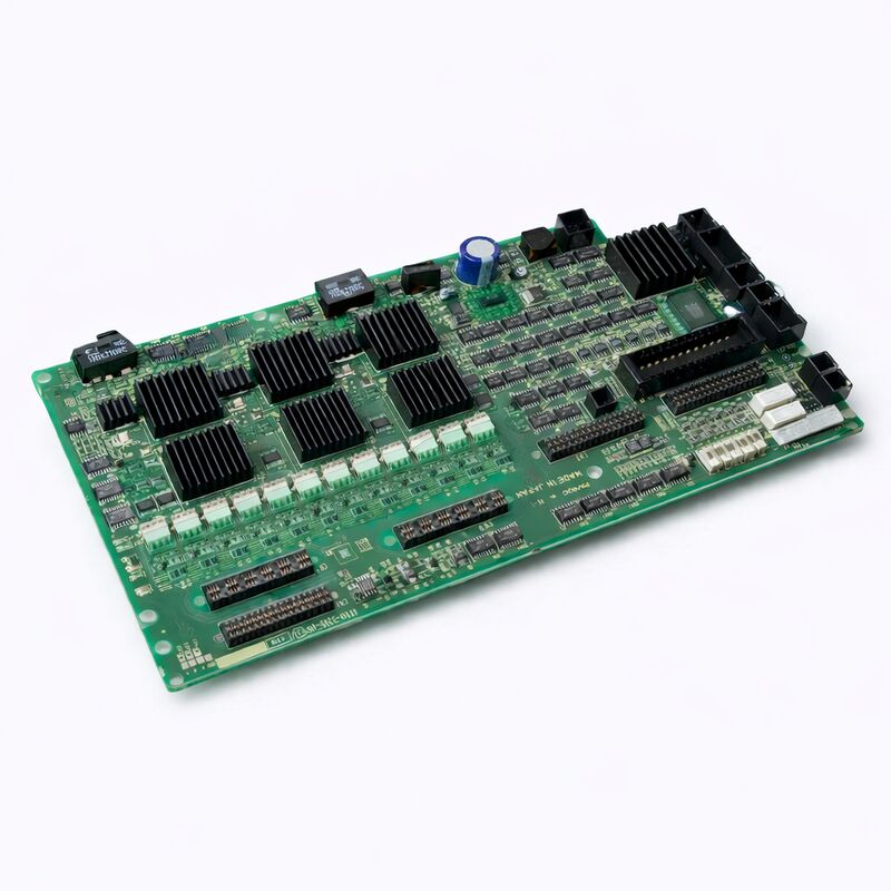
The FANUC A16B-3200-0610 is the control intelligence layer of the A06B-6107 — FANUC's 6-axis integrated servo amplifier for the R-J3iC and R-30iA robot generation.
Within the physical enclosure of the A06B-6107 amplifier, two types of circuit boards operate in partnership: the power boards (A20B-2101-0224 and A20B-2101-0234/0221/0230, depending on the specific H-series variant) that handle the high-current IGBT switching and DC bus rectification, and the A16B-3200-0610 control top board that provides all the digital intelligence — the servo algorithm execution, the FSSB communications, the fault monitoring, and the LED diagnostics.
The name "top board" is both physically and functionally accurate: in the A06B-6107 amplifier's physical layout, the A16B-3200-0610 is mounted on top of the power boards, accessible from the front of the amplifier unit.
This front-accessible mounting is an important serviceability feature in FANUC's robot drive design — the control board, which is the more frequently serviced component, can be accessed without disassembling the full amplifier or disturbing the power section wiring.
Understanding why one control board serves all six axes requires understanding the A06B-6107's design philosophy. Rather than providing six separate amplifier cards (one per joint), FANUC designed the A06B-6107 as an integrated unit where a single power section shares the rectified DC bus across six axis drives, and a single control board manages all six axes' current loops and FSSB communication simultaneously.
This integration reduces the overall amplifier footprint, simplifies wiring between the drive cabinet and the robot controller, and concentrates maintenance to a smaller number of distinct serviceable components.
Key Specifications
| Parameter |
Value |
| Function |
6-axis servo drive control (top) board |
| Compatible Amplifier |
A06B-6107-H001/H002/H007 series |
| Compatible Controllers |
R-J3iC, R-30iA |
| Interface |
FSSB fibre-optic |
| Axes Controlled |
6 (J1 through J6) |
| Power Board Partner |
A20B-2101-0224/0234/0221/0230 |
| Origin |
Japan (manufactured in Japan) |
The A06B-6107 in the R-30iA Robot System — Architecture Context
In the R-30iA controller cabinet, the A06B-6107 6-axis servo amplifier is a core component.
The R-30iA's compact drive section is designed to fit within the robot controller enclosure itself — unlike earlier robot generations where the drive unit was a large separate rack, the R-30iA's integrated design puts the servo amplifier, the main PCB, the safety board, and the power supply all within a single controller unit that can be mounted close to or on the robot base.
The signal flow from robot programme to robot motion passes through the A16B-3200-0610 as follows: the robot controller's main CPU board (A16B-3200-0600 or related variant) sends joint position commands and velocity commands for all six axes via the FSSB fibre-optic link.
The A16B-3200-0610 receives these commands, decodes them from the FSSB serial protocol, and generates the appropriate current references for each of the six axis current control loops. It simultaneously receives encoder feedback from the six joint servomotors through the servo amplifier's feedback connectors, closes the velocity and position loops for each axis, and outputs the PWM gate drive signals to the power boards' IGBT transistors that actually switch the motor current.
This entire control cycle — command reception, feedback processing, loop closure, gate drive output — repeats every 250µs (at 4kHz PWM frequency) for all six axes simultaneously. The control board's processor handles this computational load without interruption for the life of the robot, which in typical welding and handling applications may run three-shift production for 10–20 years.
FSSB — Why Fibre Optic for Robot Servo Communication
The choice of fibre-optic FSSB rather than copper wire for communication between the controller and the servo amplifier control board is deliberate and significant.
FANUC robot cabinets contain substantial electromagnetic interference sources: the servo amplifier's IGBT transistors switching at 4kHz with fast rise times, the regenerative circuit's discharge pulses, and the 24VDC relay switching for machine I/O.
Any copper signal cable running near these sources picks up interference that, at the microsecond timing resolution required by the servo loop, could corrupt data.
Fibre-optic cables are inherently immune to electromagnetic interference — light does not experience the same inductive coupling and capacitive crosstalk that afflicts copper conductors in high-noise environments.
The FSSB fibre-optic cable between the controller main board and the A16B-3200-0610 carries deterministic, error-free digital data regardless of what is happening in the servo amplifier's power section just centimetres away.
This is why FSSB connection faults caused by damaged fibre cables produce immediate, consistent FSSB alarm codes rather than intermittent unexplained servo errors.
Diagnosing A16B-3200-0610 Faults vs Power Board Faults
The A06B-6107 contains both the A16B-3200-0610 control board and the power circuit boards. When a robot axis alarm occurs, distinguishing between a control board fault and a power board fault requires understanding each board's failure signatures:
Control board failures typically affect multiple axes simultaneously (since one board controls all six) or affect the entire FSSB communication, presenting as all-axis servo alarms on startup rather than single-axis alarms during operation.
The LED array on the A16B-3200-0610's face shows system alarm codes when the board's self-diagnostics detect a fault.
Power board failures typically present as single-axis or paired-axis alarms (since the power section is sometimes organised in paired configurations), often with alarm codes indicating overcurrent, IPM alarm, or DC bus fault on specific axes.
The board-specific LED or indicator for the affected axis shows the alarm.
The presence of multiple all-axis alarms at startup, combined with the FSSB link failing to establish, points strongly to the A16B-3200-0610.
A single-axis IPM alarm during a specific motion (particularly one involving rapid acceleration of a heavily loaded joint) points to the power section.
FAQ
Q1: Can the A16B-3200-0610 control board be replaced without replacing the power boards?
Yes. The A16B-3200-0610 is a physically distinct board from the power circuit boards within the A06B-6107 amplifier, and the two types can be replaced independently. In practice, when a control board fails, the power boards are typically inspected but not automatically replaced.
Conversely, when a power board fails (IPM module failure, for example), the A16B-3200-0610 control board is usually retained unless the power failure also damaged the control board through a voltage event.
Access to the control board in the A06B-6107 follows the manufacturer's disassembly procedure described in the R-30iA maintenance manual.
Q2: After replacing the A16B-3200-0610, do robot programmes and calibration data need to be reloaded?
The A16B-3200-0610 control board does not store robot programmes, mastering data, or configuration data — these are held in the robot controller's main board (specifically in the SRAM and FROM modules).
Replacing the servo amplifier control board does not affect any data stored in the controller.
However, when the robot is powered up after amplifier replacement, the robot's mastering (absolute encoder reference positions for each joint) should be verified — while the data itself is not lost, any disturbance of the absolute encoder battery connection during amplifier service could affect mastering data.
Confirm robot accuracy with a test programme before returning to production.
Q3: The A06B-6107 generates alarm "SRVO-047 Servo motor velocity error" on multiple axes simultaneously. Does this confirm the A16B-3200-0610 has failed?
SRVO-047 on multiple axes simultaneously is consistent with an FSSB communication failure — the controller's main board cannot synchronise velocity command data exchange with the servo amplifier control board.
This alarm points to the FSSB connection (fibre-optic cable, connectors), the A16B-3200-0610's FSSB receiver circuit, or the controller main board's FSSB transmitter circuit.
Before replacing the A16B-3200-0610, inspect and clean the FSSB fibre-optic cable's connectors and verify the cable is not bent at a radius smaller than its specified minimum bend radius.
A damaged fibre cable is more common than a failed board and costs much less to replace.
Q4: What is the expected service life of the A16B-3200-0610 in a production welding robot?
There is no single answer — service life depends heavily on the operating environment (ambient temperature, contamination level, vibration exposure), the quality of cabinet cooling (insufficient cooling is the single most common accelerant of electronic component aging), and whether any voltage events (power surges, amplifier bus discharge incidents) have occurred. In clean, temperature-controlled environments with adequate cabinet cooling and no power events, A16B-3200-0610 boards routinely operate for 15–20 years without failure.
In hot, contaminated environments with variable power quality, failures at 7–10 years are not uncommon.
Preventive maintenance including cabinet cleaning, cooling fan inspection, and capacitor replacement at the 10-year mark significantly extends component life.
Q5: How is the A16B-3200-0610 sourced correctly to ensure compatibility with the specific A06B-6107 variant?
The A06B-6107 servo amplifier comes in multiple H-series variants (H001, H002, H007, and others), each configured for different robot models with different motor sizes and ratings.
The A16B-3200-0610 control board is the common control board across these variants, with the variation between variants carried by the different power circuit board specifications.
The A16B-3200-0610 part number is sufficient for ordering the correct control board — no additional H-series variant specification is needed for the control board itself.
Confirm the part number against the label on the installed board before ordering.

 Your message must be between 20-3,000 characters!