FANUC A16B-3200-0612 | 6-Axis Servo Drive Amplifier PCB — A16B-3200 Series, Robot / CNC Servo Control Board, Industrial Spare Part, Japan Origin
Overview
The FANUC A16B-3200-0612 is a servo drive amplifier PCB within FANUC's A16B-3200 series — the family of printed circuit boards spanning FANUC's CNC and robot control platforms from the late 1990s through the 2010s.
The A16B-3200 series is broad: it encompasses main CPU boards, robot main boards, servo drive control PCBs, and communication interface boards across multiple FANUC product generations.
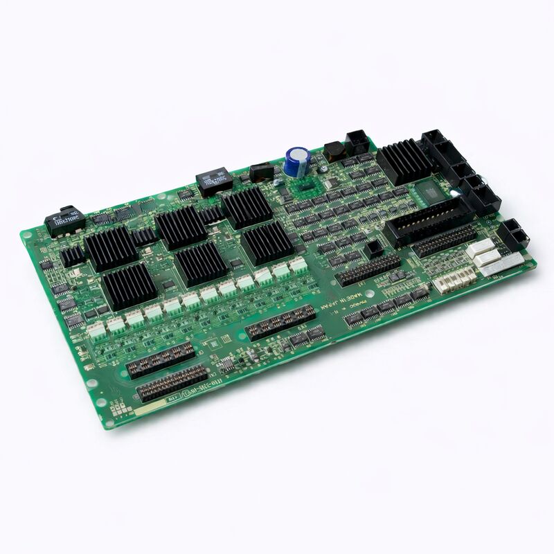
The -0612 variant's identity as a 6-axis servo drive amplifier PCB is confirmed by its physical construction — multiple high-power IC packages with heatsink assemblies arrayed across the board, each responsible for the gate drive signals to the IGBTs of one servo axis.
In a FANUC robot or multi-axis CNC drive cabinet, the servo control electronics sit between the CNC/robot controller's command output and the physical IGBT power stage that delivers current to the servo motors.
The A16B-3200-0612 occupies this critical intermediary position — it receives axis position and velocity commands from the robot or CNC CPU, executes the real-time servo control loop calculations, and generates the PWM signals that drive the power semiconductors.
Without a functional servo control PCB, no axis motion is possible, regardless of the health of the motor, the mechanical drive train, or the power supply.
The R-30iA Mate controller in which the A16B-3200-0612 was identified is FANUC's compact robot controller designed for smaller robots — the R-2000iA Mate, M-10iA, M-20iA, and related compact robot series commonly found in assembly, material handling, welding, and pick-and-place applications.
The R-30iA Mate's compact form factor integrates the power supply, amplifier, and control electronics in a densely packaged cabinet, making board-level serviceability the preferred maintenance approach rather than full controller replacement.
Key Specifications
| Parameter |
Value |
| Series |
A16B-3200 |
| Function |
6-axis servo drive amplifier PCB |
| Configuration |
Multi-IC with heatsink assemblies |
| Known Application |
R-30iA Mate robot controller |
| Origin |
Japan |
| Status |
Discontinued spare |
Six-Axis Servo Control — The Architecture Behind the Board
A 6-axis servo control PCB handles the simultaneous, independent control of six servo motor axes — the six joints of a typical industrial robot arm (J1 through J6).
Each axis requires its own control loop executing at the PWM carrier frequency (typically 4–8kHz): reading the joint encoder position, comparing it to the commanded position, computing the current reference through the velocity and position error, and outputting the appropriate PWM duty cycle for the axis's IGBT bridge.
All six loops execute in parallel, every PWM cycle, without interrupting each other.
The heat sinking visible on the A16B-3200-0612 reflects the thermal load of running six high-frequency gate drive circuits simultaneously.
Gate drive ICs dissipate power proportional to the gate charge of the IGBTs they drive, the gate drive voltage, and the switching frequency.
At 6kHz PWM across six axes, the combined gate drive dissipation is significant — the heatsinks ensure the gate drive ICs stay within their maximum junction temperature, preventing thermally-induced drift that would degrade servo performance or cause premature IC failure.
Identifying a Failed A16B-3200-0612
When the servo drive amplifier PCB fails in an R-30iA Mate or similar system, the robot controller cannot establish servo ready status.
The pendant typically displays alarms in the servo system category — SRVO-alarm codes in FANUC robot terminology — that indicate axis-level servo communication or drive faults.
Common presentations include:
Multiple axes simultaneously alarm: Because the A16B-3200-0612 handles all six axes, a board failure often affects all axes simultaneously rather than just one. A single-axis servo fault, by contrast, is more likely a motor, cable, or encoder problem than a board failure.
Servo ready cannot be established after power cycle: The drive initialisation sequence, which includes the servo amplifier board confirming its power supplies and gate driver circuitry, fails repeatedly despite clear power supply voltages.
Specific alarm codes: SRVO-047 (servo motor velocity error) on multiple axes, or communication-type servo alarms, combined with the absence of any mechanical or motor fault, points to the amplifier PCB as the fault source.
FAQ
Q1: Can the A16B-3200-0612 be used in systems other than the R-30iA Mate, and how is compatibility confirmed?
The A16B-3200-0612 was identified in R-30iA Mate controllers, but the A16B-3200 series spans multiple FANUC platforms. Compatibility with a specific system requires matching the board's connector layout, slot dimensions, and interface protocol to the target system's backplane and servo drive architecture.
Before ordering for a different system than the R-30iA Mate, confirm the part number against the controller's maintenance manual or spare parts list.
Fitting a board with incompatible pinouts or protocols can damage both the board and the system.
Q2: The board was removed from a decommissioned machine and not separately tested. What are the risks?
An untested board removed from a decommissioned system represents an unknown quality level — it may be fully functional, or it may have failed from the same event that decommissioned the machine.
Before installation in a production system, the board should be tested on a compatible test rig if possible, or installed with full awareness that the first power-up is effectively a field test. Having a backup plan (another spare board, or a repair centre on standby) before installing an untested board in a production robot minimises downtime risk.
Q3: What tools or test rigs are needed to verify the A16B-3200-0612 before installation?
Proper testing requires a compatible FANUC robot or CNC controller test rig — the same controller type the board is designed for — with functional servo amplifier power supplies, a set of servo motors (or load resistors) connected, and the ability to execute robot motion commands.
FANUC specialist repair centres maintain such test rigs specifically for board-level verification.
Without a compatible rig, functional testing on the target production machine is the only option, which carries the risk of extended downtime if the replacement board is also faulty.
Q4: The heatsinks on three of the chips are missing from the board. Does this affect functionality?
Missing heatsinks on gate drive ICs increase the risk of thermal failure during operation. Gate drive ICs without heatsinks may run within specification at low duty cycles or low ambient temperature, but can overheat under sustained high-frequency operation in a warm cabinet environment.
Before installation, the missing heatsinks should be replaced with appropriate thermal compound and equivalent heatsink hardware.
The IC package size and power dissipation determine the correct heatsink specification — consult the relevant IC datasheet for thermal resistance requirements.
Q5: What backup or documentation should be prepared from the original machine before the A16B-3200-0612 is replaced?
For robot systems, back up: all robot programmes (PROG screen — ALL.TP backup), all system parameters (SYSVAR file), mastering data (joint encoder reference positions — critical for robot accuracy after board replacement), and any I/O configuration data.
For CNC systems, back up: all CNC parameters, PMC ladder, and part programmes.
The servo control PCB itself does not store this data (it is stateless from the machine data perspective), but the replacement procedure may require a servo reboot sequence that clears certain volatile servo states — all critical data should be externally backed up before beginning any board replacement in a production system.

 Your message must be between 20-3,000 characters!