FANUC A20B-1000-0560 | 6050 Single-Axis Analog AC Servo Drive PCB — Rev E / F, Model 0–30 AC Servo Motors
Part Number: A20B-1000-0560
Manufacturer: FANUC Corporation (Japan)
Product Type: Single-Axis Analog AC Servo Drive Control PCB (VCU)
Board Series: A20B-1000
Drive Family: A06B-6050 Series (Analog AC Velocity Control Units)
Overview
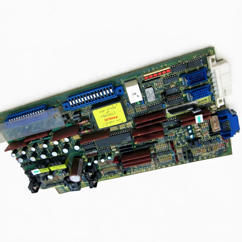
The A20B-1000-0560 is the control PCB for FANUC's 6050 series single-axis analogue AC servo drive units — the Velocity Control Unit (VCU) card that sits inside the open, anodised-frame 6050 drive enclosure and handles all the servo control processing.
It represents FANUC's first generation of AC servo drive electronics, introduced alongside the iconic red-cap AC servo motors that began replacing DC servo systems in machine tools during the 1980s.
The term "VCU" — Velocity Control Unit — describes the control architecture these drives use. The CNC controller sends an analogue ±10V velocity command signal to the drive. The A20B-1000-0560 receives this command, compares it to the motor's actual speed derived from the tachometer feedback, and adjusts the output current to the motor to close the velocity loop.
This is a fully analogue control scheme, fundamentally different from the digital serial control introduced in later drive generations.
The analogue architecture is simple and robust — the drive does not require firmware updates or serial parameter configuration, and its behaviour is determined entirely by the hardware.
The A20B-1000-0560 covers the full range of the 6050 drive series — from the smallest models driving Model 0 and Model 5 AC servo motors up to the large H104 drives powering Model 20S and Model 30 motors.
This broad coverage from a single board part number reflects the common analogue control architecture that all 6050 single-axis drives share.
Key Specifications
| Parameter |
Value |
| Part Number |
A20B-1000-0560 |
| Manufacturer |
FANUC Corporation |
| Product Type |
Single-Axis Analog Servo Drive PCB |
| Board Series |
A20B-1000 |
| Drive Series |
A06B-6050 (Single-axis analog AC VCU) |
| Compatible Drives |
A06B-6050-H002, H102, H103, H104, and variants |
| Motor Coverage |
Model 0 through Model 30 AC servo (red cap) |
| Control Type |
Analogue VCU (±10V velocity command) |
| Available Revisions |
Rev E, Rev F, and other variants |
| Origin |
Japan |
| Condition Available |
Refurbished / Exchange / Repaired |
The 6050 Drive Family and the Red Cap AC Servo Generation
The A06B-6050 series drives were FANUC's first mass-market AC servo drive family — the product that put AC servo technology into machine tools at scale. Before them, DC servo systems (the 6042 and 6044 series) dominated.
The 6050 series changed that. The AC servo motor's brushless construction eliminated the DC motor's maintenance-intensive brush and commutator, and the AC motor could be sealed more easily against coolant and swarf, making it far more suitable for machine tool environments.
The drives that housed the A20B-1000-0560 are recognisable by their anodised metal frame construction — an open frame design with the control card mounted visibly at the top and the power transistor assembly below.
The "red cap" motors they drove took their informal name from the distinctive red-painted end caps on the first generation of FANUC AC servo motors.
Machines from the mid-1980s through the mid-1990s were equipped with these systems in large numbers — turning centres, machining centres, grinders, and robots all across the industry.
Revision Levels — Why They Matter
The A20B-1000-0560 exists in multiple hardware revision levels, designated by letter suffixes (E, F) and alphanumeric codes.
These revisions are not minor cosmetic changes. They can involve differences in component values, circuit modifications that affect control loop behaviour, and hardware modifications that address specific compatibility issues with particular motor or controller combinations.
The wrong revision in a drive may produce hunting, instability, or immediate servo alarms.
Revisions progress from earlier to later — later revisions typically supersede earlier ones and may be usable in place of earlier revisions in some drive configurations. The general principle is that a same-or-later revision can usually substitute for the specified revision, but a much earlier revision should not be substituted for a later one without verification.
The specific revision required for a particular drive unit is determined by what was originally fitted — check the revision marking on the original board's label before ordering a replacement.
Fault Symptoms and the Role of the Control PCB
In the 6050 drive's two-board architecture, the power section handles the high-voltage switching and the control card handles all the signal processing. When the drive fails, identifying which section is at fault directs the repair approach.
Control card failures typically produce control-related symptoms — oscillation in the motor, inability to reach commanded speed, velocity feedback errors, or drive alarm codes related to the control signal path.
Power section failures produce power-related symptoms — overcurrent alarms, transistor faults, or missing output phases.
A control card fault can sometimes be identified by substituting a known-good card into the drive with the original motor connected.
If the symptom clears with the substitute card, the original control card is confirmed faulty.
This swap test is the most definitive diagnostic step.
FAQ
Q1: The 6050 drive's motor hunts (oscillates) continuously at low speed and produces a characteristic buzzing. The power transistors have been confirmed good. Is the A20B-1000-0560 the likely cause?
Low-speed hunting and oscillation in an analogue VCU drive is a classic control loop fault. It indicates the velocity loop gain is either too high — producing instability — or that a component in the control card's feedback processing has drifted.
Capacitor aging in the tachometer feedback filter or the error integrator circuit is the typical culprit. With the power section confirmed good, the control card is the next investigation point.
If a tested spare is available, substitution confirms whether the card is the source.
Q2: The drive's alarm LED is lit but no specific alarm code is visible. The motor will not rotate. What should be checked on the A20B-1000-0560?
An illuminated alarm LED without motor rotation indicates the drive has detected a fault condition and inhibited its output.
On the 6050 control card, check for any components that show visible signs of failure — burnt components, damaged capacitors, or obviously failed transistors on the card itself.
Check the velocity command input voltage from the CNC — if the CNC is not delivering a valid command signal, the drive may not respond.
Verify the tachometer feedback signal from the motor is reaching the card.
Systematically isolating whether the fault is in the command input, the feedback path, or the card's internal processing narrows the diagnosis.
Q3: The available replacement A20B-1000-0560 is Rev E but the original was Rev F. Can Rev E be used?
Rev E is an earlier revision than Rev F. Using an earlier revision where a later one was specified risks introducing a compatibility issue that the later revision was specifically released to address.
This substitution should be approached with caution. Verify that the specific differences between Rev E and Rev F for this drive model do not affect the motor and load combination being used.
In urgent situations, the earlier revision may function acceptably, but the preference is always to match or exceed the originally specified revision.
Q4: The 6050 drive was running correctly but has been in storage for five years. On reinstallation, it shows a velocity loop alarm immediately. The motor is confirmed good. What might have changed?
Storage over several years degrades electrolytic capacitors on the control card. When re-energised after extended storage, capacitors that have lost capacitance or developed high leakage current can cause velocity loop instability or alarm conditions.
Reforming the capacitors by gradually increasing the applied voltage over several hours can recover some capacity.
In many cases, however, a refurbishment — replacing all electrolytic capacitors on the control card with new parts — is the reliable solution for a drive returning to service after extended storage.
Q5: Multiple axes on the same machine use the same A06B-6050 series drive, each with an A20B-1000-0560. Should all cards be replaced at the same time if one fails?
Replacing all cards simultaneously is rarely necessary and is economically inefficient. Each card ages according to its own duty cycle.
A card on a heavily used axis may be near the end of its service life while a card on a lightly used axis is perfectly functional.
Replace the failed card and monitor the others. If the machine runs a very high-duty cycle and the drives were all installed at the same time, a case can be made for proactive refurbishment of the remaining cards — replacing the electrolytic capacitors — before they show symptoms, but outright replacement of functional cards is not routinely necessary.

 Your message must be between 20-3,000 characters!