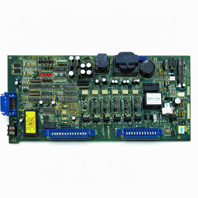
FANUC A20B-1003-0090 | S Series Single-Axis AC Servo Control PCB — 6058 Drive, Japan Origin
Part Number: A20B-1003-0090
Manufacturer: FANUC Corporation (Japan)
Product Type: Single-Axis AC Servo Control PCB
Board Series: A20B-1003
Drive Compatibility: A06B-6058 series (S Series single-axis AC servo amplifiers)
Motor Compatibility: 0S through 30S/3000 series AC servo motors
Interface: PWM (digital, from CNC controller)
Compatible CNC: Series 0-A, 0-B, 0-C; early Series 15, 16, 18 (Model A)
Drive Models: A06B-6058-H004, H005, H006, H012, H013, H025
Overview
The A20B-1003-0090 is the control PCB for FANUC's S Series single-axis AC servo amplifier units in the 6058 family — described by specialists as one of the most widely deployed servo control boards in FANUC's history.
It is the front-face board of the open-frame 6058 series drive units, housing the digital servo control electronics while the companion power board handles the power stage.
Every A06B-6058-H004, H005, H006, H012, H013, and H025 drive unit — across the full range of FANUC S-series single-axis drives — was fitted with this board as the control intelligence.
The S Series digital drives represented FANUC's transition from analogue servo systems to fully digital servo control.
The A20B-1003-0090 received PWM (pulse-width modulation) commands from the CNC controller — a digital, noise-immune signal encoding the velocity demand — and processed the encoder position feedback from the servo motor.
From these inputs, the board ran the servo control algorithm: the current command went to the power board, which drove the motor; the position feedback went back to the controller, which updated the next position demand.
This board served an enormous installed base. FANUC's Series 0 controllers in the 0-A, 0-B, and 0-C generations were among the most commercially successful CNC controllers ever produced, and the S Series drives were the servo system of choice for these controllers through much of their production life.
Early Series 15, 16, and 18 Model A systems also used these drives extensively.
The result is a huge population of machines — turning centres, machining centres, and grinding machines from the late 1980s through the mid-1990s — that still depend on functional A20B-1003-0090 boards to operate.
Key Specifications
| Parameter |
Value |
| Part Number |
A20B-1003-0090 |
| Manufacturer |
FANUC Corporation |
| Product Type |
Single-Axis AC Servo Control PCB |
| Board Series |
A20B-1003 |
| Drive Compatibility |
A06B-6058-H004, H005, H006, H012, H013, H025 |
| Motor Coverage |
0S through 30S/3000 |
| Interface |
PWM digital (from CNC controller) |
| Compatible CNC |
Series 0-A/B/C; Series 15/16/18 Model A (early) |
| Construction |
Mixed through-hole and SMT |
| Origin |
Japan |
| Companion Power Board |
A20B-1003-0081 |
| Condition Available |
New (surplus) / Refurbished / Repaired |
The S Series Architecture
The 6058 drive series has a two-board internal structure that separates the control electronics from the power electronics.
This separation is architecturally deliberate and practically important. The power board handles high-current, high-voltage switching — the IGBTs that convert DC bus voltage to the variable AC that drives the motor, and the current sensing that measures the actual motor current.
The control board handles the signal-level processing — the PWM input from the CNC, the encoder feedback from the motor, and the algorithm that computes the current command.
The A20B-1003-0090 is the control board. It receives the PWM command from the controller and reads the motor's pulse coder — a digital encoder that provides position feedback as a square wave signal.
The board counts encoder pulses to track actual motor position, computes the position error, runs the velocity loop, and generates the current command for the power board.
The power board acts on this command to deliver the precise motor current needed.
This dual-board structure means that many drive failures are attributable to one board only.
A power transistor failure on the power board typically leaves the control board intact.
An alarm code fault on the control board's electronics typically leaves the power board undamaged.
Targeted board-level diagnosis and replacement of only the failed board is often possible, avoiding the cost of replacing the complete drive unit.
Motor Coverage: 0S through 30S
The "S" series motor naming indicates the motor's continuous stall torque class, with the number representing the torque rating. The 0S is the smallest — a compact, light-duty motor for light-axis applications.
The 10S and 20S are the most commonly encountered in general machining applications.
The 30S represents the upper end of the range this board serves.
The A20B-1003-0090 covered essentially the entire practical motor range for the single-axis 6058 drives, except for a few specialised variants (the H002, H003, and H007 models had dedicated control PCBs for their specific requirements).
This universality — one control board across seven different drive model variants — was part of what made this board so prevalent. Spares stockholding was simplified: one board type covered the majority of the 6058 fleet.
PWM Interface and Compatibility with CNC Controllers
The PWM interface connected this drive to the CNC controller. The controller generated six PWM signals — PWMA through PWMF — representing the three-phase sinusoidal modulation for the IGBT bridge.
Additional signals provided alarm feedback (ALM1 through ALM8), drive ready (DRDY), and enable (MCON).
The complete set of signals constituted the drive-controller interface.
This PWM interface was the standard for FANUC's digital servo generation.
Controllers that supported it — the full 0-series range and the early 15/16/18 family — could drive any compatible 6058 unit.
The specific controller address assignment and parameter configuration mapped the correct controller output signals to each drive unit in the machine.
FAQ
Q1: The 6058 drive shows an alarm code indicating overcurrent on start-up. The motor and motor cable have been confirmed undamaged. Could the A20B-1003-0090 be the cause?
Yes. The control board generates the current command that the power board executes.
If the control board's current command circuit produces an incorrect or excessive command at startup — due to a failed component in the command generation circuitry — the drive generates an overcurrent alarm even with a healthy motor.
Test by substituting a confirmed-good A20B-1003-0090 in the drive while keeping all other components unchanged. If the alarm clears, the original control board is faulty.
Q2: The drive alarm codes include a "FAL" alarm (internal fan stopped). Is this a control board fault?
No. FAL indicates the drive's internal cooling fan has stopped. The fan is a mechanical component independent of the control board.
Check the fan — it may be jammed by debris or its bearings may have failed.
Replace the fan with a matching replacement rated for the drive's voltage and airflow requirements.
The A20B-1003-0090 monitors the fan status and generates the FAL alarm, but the fan itself is the component to replace.
Q3: The drive ran correctly for years. Now after a summer with unusually high ambient temperatures in the cabinet, it produces DRDY (drive ready) failures intermittently. What should be investigated?
High ambient temperature accelerates electrolytic capacitor aging on the control board. As capacitors on the control board's power supply section degrade, the internal supply voltage develops ripple.
The control board's circuits may fail to initialise correctly when supply voltage is marginal, producing DRDY failures.
This is more likely at high ambient temperatures because the capacitors' ESR increases with temperature.
Control board refurbishment with new capacitors is the appropriate solution.
Q4: A replacement A20B-1003-0090 will be installed. Are there any configuration settings on the board that need to match the original?
The A20B-1003-0090 has switch or jumper settings that may be set for the specific drive unit and motor combination.
These settings configure the board's operation for the specific drive model and may include gain settings, axis type, and interface configuration.
Before removing the original board, document or photograph all switch and jumper positions.
Ensure the replacement board is set identically before installation.
Incorrect settings can cause alarms or incorrect servo behaviour even if the board is otherwise functional.
Q5: This board is described as one of the most widely sold FANUC servo control PCBs. Does this mean replacement boards are reliably available?
The broad historical deployment of the A20B-1003-0090 means the aftermarket supply chain is correspondingly well stocked.
Tested surplus units, professionally refurbished boards with new capacitors and functional testing under actual motor load, and exchange services are all available from specialist CNC servo parts suppliers.
The board's widespread use also means there are many technicians experienced in its diagnosis and repair.
For production-critical applications, sourcing a tested spare before the installed board fails is the most practical approach.

 Your message must be between 20-3,000 characters!