FANUC A20B-1004-0070 | CZ-Type Spindle Motor Encoder PCB — Speed Feedback / Z-Pulse Orientation
Part Number: A20B-1004-0070
Manufacturer: FANUC Corporation (Japan)
Product Type: Spindle Motor Encoder PCB — CZ Type
C-Signal and Z-Signal — What Each Does
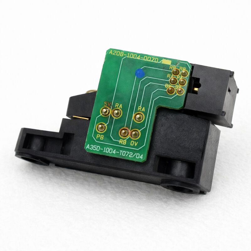
The A20B-1004-0070 is a CZ-type spindle encoder PCB — the board inside the spindle motor housing that reads the rotating encoder assembly and generates two distinct feedback signals for the spindle drive system.
C-signal (speed feedback): Provides the spindle amplifier with the motor's actual rotational speed. The amplifier compares this continuously against the commanded speed and adjusts output current to compensate for load variations during cutting. Without a valid C-signal, speed regulation collapses and the drive cannot hold the programmed RPM.
Z-signal (orientation reference): Generates one pulse per complete shaft revolution. The CNC uses this pulse as the angular reference when executing spindle orientation — the M19 function that stops the spindle at a precise angle for automatic tool changing. The Z-signal is only needed for orientation, not for continuous cutting, which is why a damaged Z-signal path produces a specific symptom: normal spindle speed during cutting, but M19 faulting every time.
That symptom — orientation fails, cutting runs correctly — points directly to the Z-signal path and helps isolate the encoder PCB as the probable fault.
The PCB and the Rotor Are Two Separate Parts
The A20B-1004-0070 is the electronic portion of the encoder assembly. The rotor — the mechanical element that rotates with the motor shaft and passes in front of the PCB's sensing elements — is a separate component with its own FANUC part number. When replacing the PCB, the original rotor can be reused if undamaged.
After a spindle crash, the rotor may have shifted or fractured even when it appears visually intact — a shifted rotor changes the air gap between the sensing elements and the rotor surface, producing weak or erratic signals from an otherwise functional new PCB. Always inspect the rotor and confirm the correct air gap after any crash-related encoder replacement.
Key Specifications
| Parameter |
Value |
| Part Number |
A20B-1004-0070 |
| Encoder Type |
CZ (speed + Z-pulse) |
| Series |
A20B-1004 |
| Compatible CNC |
Series 15M and compatible |
| Z-Signal |
1 pulse / revolution (orientation) |
| Origin |
Japan |
FAQ
Q1: Spindle orientation (M19) always faults, but cutting at speed is normal. Is the A20B-1004-0070 the cause?
This symptom specifically implicates the Z-signal path — the one-per-revolution pulse used for orientation. Verify the Z-signal at the encoder connector with an oscilloscope while rotating the shaft. A clean single pulse per revolution confirms the signal is present. Absent or very weak Z-pulse with a confirmed correct air gap indicates a failed PCB. If the Z-pulse is present but orientation still fails, check the spindle orientation parameter settings in the CNC before replacing the board.
Q2: The spindle motor was in a crash. The encoder PCB looks undamaged but position errors appear. What should be checked?
After a crash, the rotor may have physically shifted on the shaft or been damaged without visible cracking. A shifted rotor narrows or distorts the air gap between it and the PCB sensing elements, producing weak or erratic signals regardless of PCB condition. Remove the encoder cover, inspect the rotor, and verify the air gap meets the specification in the spindle motor maintenance documentation before replacing the PCB.
Q3: Can the A20B-1004-0070 be tested on a bench outside the motor?
No practical bench test is possible. The PCB generates signals only when the rotor passes across its sensing elements. Functional testing requires the PCB to be installed in the motor with the shaft rotating — either in the machine or on a test stand. Confirm the C and Z signals at the encoder connector during slow shaft rotation.
Q4: After replacing the PCB, spindle speed is erratic under cutting load but orientation works correctly.
Erratic speed under load with correct orientation indicates a C-signal issue. The Z-signal (orientation) is functioning, but speed feedback is intermittent or noisy. Check the encoder cable and connector for intermittent contact. Measure the C-signal amplitude at the amplifier input — a signal below the amplifier's minimum threshold produces unreliable speed feedback even if the signal is clean at the PCB connector.
Q5: The encoder housing has coolant contamination. Can the board be cleaned and reused?
Light surface contamination can be addressed with electronics-safe contact cleaner. However, coolant inside the encoder housing indicates a seal failure that will recur. Identify and repair the failed seal before reinstalling the encoder — coolant on the sensing elements degrades signal quality even without physically damaging the PCB. Both the cleaning and the seal repair are needed for reliable long-term operation.

 Your message must be between 20-3,000 characters!