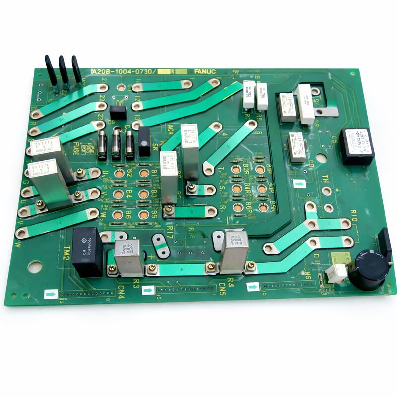
FANUC A20B-1004-0730 | AC Spindle Amplifier Power Board — A06B-6064 Series, Japan Origin
Part Number: A20B-1004-0730
Manufacturer: FANUC Corporation (Japan)
Product Type: Spindle Amplifier Power Board (Power Card)
Board Series: A20B-1004
Compatible Drive Unit: FANUC AC Spindle Servo Unit A06B-6064 series
Compatible Motors: Spindle models 6S, 8P, 12P (9A50 software)
Overview
The A20B-1004-0730 is the power board — also called the power card — for FANUC's A06B-6064 series AC spindle servo unit.
The 6064 is one of FANUC's established AC spindle amplifier platforms, used extensively in CNC turning centres and machining centres equipped with FANUC spindle motors in the 6S, 8P, and 12P output class.
Within the complete spindle drive unit, the power board is the component that interfaces between the control electronics and the power transistors — it carries the gate drive signals that switch the IGBT output transistors, and it processes the current feedback signals that the control board uses to regulate spindle motor current.
The A06B-6064 drive unit is a field-serviceable assembly.
It contains multiple boards: the main control board, an auxiliary control card, and this power board. When a spindle amplifier develops a fault, identifying which board within the unit has failed allows targeted replacement rather than complete drive unit replacement.
The A20B-1004-0730 is the power-stage board — the component closest to the high-power switching circuits.
The power board is mounted within the spindle amplifier housing. It connects to the IGBT transistor modules on the heatsink, the bus voltage measurement circuits, and the current sensing elements.
Its job is to take the low-power control signals from the control board and translate them into the gate drive levels required to switch the high-current output transistors that power the spindle motor.
Key Specifications
| Parameter |
Value |
| Part Number |
A20B-1004-0730 |
| Manufacturer |
FANUC Corporation |
| Product Type |
Spindle Amplifier Power Board |
| Board Series |
A20B-1004 |
| Compatible Drive Unit |
FANUC A06B-6064 AC Spindle Servo Unit |
| Compatible Motors |
Spindle models 6S, 8P, 12P |
| Software Compatibility |
9A50 series spindle software |
| Origin |
Japan |
| Operating Temperature |
0 – 55°C (as installed in drive unit) |
| Storage Temperature |
−20 – 55°C |
| Condition Available |
New (surplus) / Refurbished / Repaired |
The A06B-6064 Drive — Architecture and Board Layout
FANUC's 6064 series spindle drive units are three-phase AC inverter drives designed to power FANUC AC spindle motors. The drive converts the incoming three-phase AC supply to DC, then reconstructs variable-frequency, variable-voltage AC to control the motor.
The power transistors (IGBTs) that perform the AC reconstruction are mounted on the heatsink and are the highest-power elements in the drive.
The A20B-1004-0730 power board occupies the layer between the control electronics and these power transistors.
The control board generates the PWM control signals that define how and when each output transistor should switch.
These signals are at logic level — too low in voltage and too weak in current to directly drive the IGBT gates.
The power board contains gate driver circuits that amplify these control signals to the levels the IGBTs require.
It also contains the bootstrap circuits and level shifters needed to drive the high-side transistors in each phase leg.
Additionally, the power board processes the current feedback signals from the drive's current sensors.
These signals represent the actual motor phase currents. The power board conditions these signals and passes them back to the control board, which uses them to close the current control loop.
6064 Compatible Motor Classes
The A06B-6064 series covers drive units matched to specific FANUC spindle motor models.
The A20B-1004-0730 power board is used in drive variants compatible with spindle motor models 6S, 8P, and 12P. These designations refer to the motor's power and speed class within FANUC's AC spindle motor range.
The 6S, 8P, and 12P motors represent a range from moderate-power to higher-power spindle applications.
The 6S is a 6-output-class motor, suitable for smaller machining centres and turning centres with moderate spindle power requirements.
The 12P represents a larger motor class with higher continuous power output, used in heavier cutting applications.
The power board must match the drive unit's rated current.
A power board from a lower-rated unit installed in a higher-rated unit would be overloaded during normal operation.
Always confirm the drive unit's complete ordering number before sourcing a replacement power board.
Power Board Fault Patterns
Power board faults in spindle drives tend to produce specific alarm patterns. Gate driver failures cause one or more output phases to be absent or distorted — the motor receives unbalanced current, overheats, and the drive alarms on overcurrent or phase loss.
A damaged gate driver for a specific transistor position produces a recognisable pattern on an oscilloscope: the affected phase's output current waveform is distorted or absent.
Current measurement circuit failures produce incorrect current feedback.
The control board receives wrong current data and either commands incorrect motor currents, or the measured overcurrent alarm triggers without a genuine overcurrent event.
Bus voltage measurement circuit failures produce incorrect DC bus voltage readings.
The drive may fault on overvoltage or undervoltage alarms that do not correspond to the actual bus voltage.
FAQ
Q1: The spindle drive shows an overcurrent alarm at every attempt to accelerate the spindle, but the motor shows no sign of overload. The control board tests as good. Is the power board the likely fault?
An overcurrent alarm with no actual motor overload, and with the control board confirmed good, points to the power board's current measurement circuit.
A failed current sensor interface or measurement IC on the power board produces false overcurrent readings that trigger the alarm on acceleration.
Test the current feedback signal at the power board's output connector during a slow, low-load spindle acceleration — if the measured current doesn't correspond to the actual motor load, the power board's measurement circuit has failed.
Q2: The spindle motor runs but produces more vibration and noise than normal, and the motor runs hot. One phase of the output current looks distorted on an oscilloscope. Is this the power board?
Distorted output current with associated motor heating and vibration is the classic signature of a gate driver failure on one output transistor position. The affected transistor is not switching correctly — it may be partially on, causing shoot-through current, or partially off, leaving one phase reduced.
The power board's gate driver for the affected phase has likely failed. Replace the power board and re-test with an oscilloscope on all three output phases.
Q3: The drive was previously repaired. The power board was replaced at that time. The drive now has a similar fault. Was the replacement power board defective, or could there be a root cause?
Recurrent power board failure after a previous replacement suggests a root cause that damaged both boards.
Common root causes include DC bus overvoltage from a faulty regenerative braking circuit, gate driver supply voltage issues, or sustained high-current overloads from mechanical problems in the spindle or spindle motor.
Investigate the root cause before installing another replacement board — without addressing the root cause, the new board will likely fail in the same way.
Q4: The spindle runs normally at low and medium speeds but faults on overcurrent at high speed only. The load does not seem excessive. What on the power board could cause this?
High-speed-only overcurrent faults with no apparent load overload often indicate a thermal issue in the power board's gate drive circuit. At high speed, the switching frequency is the same but the losses in the gate drivers and their thermal dissipation are higher.
A gate driver that is marginal but functional at lower power levels fails under the thermal stress of sustained high-speed operation.
Check the cooling air flow to the drive unit and the condition of the heatsink. If cooling is adequate and the fault persists, the power board's gate driver section has aged beyond its thermal margin.
Q5: Is it necessary to re-tune the spindle after replacing the A20B-1004-0730 power board?
The spindle control parameters — motor constants, current gains, speed regulator settings — are stored in the drive's control board and in the CNC's spindle parameters, not on the power board.
A power board replacement does not require re-tuning unless the replacement board has a different hardware revision that requires a software update.
Confirm the revision level of the replacement board matches the original, perform a test run after replacement, and verify that the spindle speed and load behaviour match the machine's specification.

 Your message must be between 20-3,000 characters!