FANUC A20B-1005-0190 | Spindle Drive Control PCB — AC Spindle Amplifier Systems
Part Number: A20B-1005-0190
Manufacturer: FANUC Corporation (Japan)
Product Type: Spindle Drive Control PCB
Board Series: A20B-1005
What This Board Does
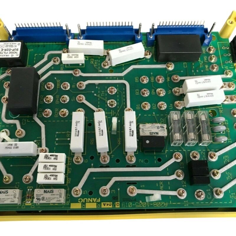
The A20B-1005-0190 is the control board inside a FANUC AC spindle drive. It handles the logic that sits between the CNC's spindle command and the actual motor output — reading the target RPM from the CNC, comparing it to actual speed feedback, adjusting the PWM output, and monitoring current, temperature, and encoder signals in real time.
It is a control-section board, not a power-stage board. That distinction matters for diagnostics. The power stage contains the IGBT transistors that switch high motor currents. The control board is the electronics that tell those transistors when to switch. Many spindle faults that look like power-stage problems — overcurrent alarms on acceleration, erratic speed — actually originate in the control electronics. A faulty gate driver IC on the control board sends incorrect timing pulses to the power transistors, and the result looks like a transistor fault. Replacing the control board is the right first step in those cases.
The A20B-1005 series covers control boards matched to specific FANUC AC spindle drive configurations, with the correct signal interface, protection logic, and communication protocol for those drives.
After Replacement
When fitting a replacement control board, verify the drive parameters. The control board stores motor-specific settings — rated current, speed calibration, application parameters. If the previous board had custom settings, restore them from a recorded parameter list before returning the spindle to production. Skipping this step is the most common cause of post-replacement issues.
Key Specifications
| Parameter |
Value |
| Part Number |
A20B-1005-0190 |
| Series |
A20B-1005 |
| Type |
Spindle Drive Control PCB |
| Operating Temp |
0–55°C |
| Storage Temp |
−20–60°C |
| Humidity |
75% RH max (non-condensing) |
| Origin |
Japan |
FAQ
Q1: The spindle shows an overcurrent alarm on acceleration. Power transistors test good. Could this board be the cause?
Yes. A faulty gate driver on the control board causes the output transistors to switch incorrectly, generating a current spike that triggers overcurrent detection — even when the transistors themselves are undamaged. Replace the control board first and verify parameters before testing under load.
Q2: Spindle speed hunts during cutting. Motor and encoder appear undamaged. What to check?
Speed hunting with an intact mechanical system points to the speed regulator or feedback processing on the control board. First confirm clean encoder pulses at the board's input. Then review the speed regulator gain parameters. If both are correct, the board's regulator circuitry may have degraded components.
Q3: After board replacement, spindle runs but orientation doesn't complete. Why?
Orientation relies on the encoder Z-pulse and orientation parameters in the drive. Confirm those parameters were transferred from the original configuration. If parameters are correct, verify the Z-signal is reaching the replacement board's correct input terminal.
Q4: The drive passes its self-test but faults on the first CNC speed command. What does this indicate?
Normal self-test but fault on the first CNC command suggests the communication interface on the control board cannot correctly interpret the serial command from the CNC. Confirm cabling between CNC and drive first. If cabling is good, the board's communication circuit is the fault.
Q5: How should this board be stored as a preventive spare?
Store in anti-static packaging at stable room temperature, away from moisture. Before storing, record the parameter settings from the installed board — a spare with documented parameters halves recovery time when the spare is eventually needed.

 Your message must be between 20-3,000 characters!