FANUC A20B-1006-0470 | Alpha PSM-15 Power Supply Module Base Wiring PCB — 17.5kW, 283–325V DC, Series 16i/18i/21i
Part Number: A20B-1006-0470
Manufacturer: FANUC Corporation (Japan)
Product Type: Alpha Power Supply Module Base Wiring Board (Power PCB / Main Board)
Board Series: A20B-1006
Compatible Module: A06B-6087-H115 (PSM-15 Alpha Power Supply Module)
Overview
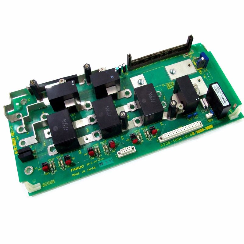
The A20B-1006-0470 is the base wiring board — the power section PCB — inside FANUC's A06B-6087-H115 Alpha Power Supply Module, the PSM-15. In the PSM-15's two-board architecture, the A20B-1006-0470 is the board where the actual power conversion happens.
It houses the three Intelligent Power Modules (IPMs) that convert incoming three-phase 200–230V AC into the regulated 283–325V DC bus that feeds all connected servo amplifier modules (SVM) and spindle amplifier modules (SPM).
The A16B-2202-0421 control card mounted above it handles the monitoring, regulation logic, and alarm management.
The PSM-15 is a mainstay of FANUC's Alpha drive system — found on thousands of CNC machine tools including lathes and machining centres equipped with Series 16i, 18i, and 21i controllers.
At 150mm wide, it is sized to power a typical mid-range drive configuration: a spindle amplifier module plus one or two servo amplifier modules from a single DC bus.
Mori Seiki SL-250B lathes, Mazak Integrex series, and many comparable mid-class machining centres from the late 1990s through 2000s were built around the PSM-15 and the drive chain it powers.
The "main board" and "power supply" designations in the A20B-1006-0470's description capture both its physical position in the module (as the base board) and its functional role (as the power stage).
The screw terminals on this board accommodate the heavy-gauge conductors carrying the 54A input current and the DC bus output current.
Multiple additional connections serve the monitoring signals, bus voltage sense, and intermodule communication that the PSM-15 exchanges with the rest of the drive system.
Key Specifications
| Parameter |
Value |
| Part Number |
A20B-1006-0470 |
| Manufacturer |
FANUC Corporation |
| Product Type |
PSM Base Wiring Board (Power Section PCB) |
| Board Series |
A20B-1006 |
| Compatible Module |
A06B-6087-H115 (PSM-15) |
| Associated Control Card |
A16B-2202-0421 |
| Module Rated Output |
17.5 kW |
| AC Input |
200–230V, 3-phase, 54A @ 200V |
| DC Bus Output |
283–325V DC |
| IPM Modules |
3 |
| Module Width |
150 mm |
| Cooling |
External heatsink + internal and external fans |
| Terminals |
Screw terminals |
| Compatible CNC |
Series 16i, 18i, 21i |
| Recommended AC Reactor |
A81L-0001-0123 |
| Origin |
Japan |
| Status |
Discontinued by Manufacturer |
IPM Technology in the PSM-15
The PSM-15 uses Intelligent Power Modules (IPMs) rather than discrete IGBT transistors. An IPM is a self-contained power module that integrates the switching transistors, gate drive circuits, and protection electronics into a single sealed package.
The protection circuits inside the IPM detect overcurrent, overtemperature, and gate drive fault conditions and respond faster than external protection circuits could.
For the PSM-15's active rectifier function, three IPMs work together to implement the six-switch bridge that converts the three-phase AC input into DC bus voltage.
Unlike a passive diode bridge, the active rectifier can control the input current waveform — drawing current in sinusoidal waves that are synchronised with the supply voltage.
This active power factor correction means the PSM-15 draws current from the grid in a way that closely resembles a purely resistive load, minimising harmonic distortion and maximising the efficiency of power transfer from the supply.
The active rectifier also enables power regeneration. When servo motors decelerate, they act as generators and return energy to the DC bus. If the bus voltage rises above the regulation threshold, the PSM-15's active rectifier can reverse the power flow and return this regenerated energy to the AC supply.
This regeneration capability reduces energy consumption in machines with frequent high-inertia deceleration cycles and eliminates the need for braking resistors in many applications.
Multiple I/O and Screw Terminal Architecture
The "multiple inputs/outputs" designation reflects the comprehensive signal termination on the A20B-1006-0470. Beyond the main AC power input and DC bus output connections, the board accommodates several additional signal circuits. DC bus voltage sensing feeds back to the control card's regulation loop.
Module temperature monitoring allows the control card to initiate protective shutdown before the IPMs reach thermal limits.
Input current monitoring provides the feedback for the active power factor correction algorithm. DC bus capacitor pre-charge current sensing manages the controlled energisation sequence at power-on.
The screw terminals on the A20B-1006-0470 are engineered for the current levels involved.
The AC input terminals carry 54A in normal operation at 200V.
The DC bus output terminals carry the total current drawn by all connected SVMs and SPMs. At these current levels, terminal torque is critical — undertorqued connections generate contact resistance, which generates heat, which accelerates insulation degradation and eventually produces a high-resistance joint that itself overheats. Periodic inspection and torque verification of all power connections is a routine maintenance task for PSM-15 installations.
Availability and Service Practice
FANUC's practice and the standard approach of specialist CNC service providers is not to supply the A20B-1006-0470 as an individual board.
The PSM-15 is serviced as a complete module — either through exchange (a refurbished tested module for the faulty one) or through drive-level repair where the specific failed component is identified and replaced.
This module-level service approach is driven by practicality.
Testing the A20B-1006-0470 requires verifying its operation under full load with all three IPMs switching at the correct duty cycle — conditions that can only be confirmed in a complete PSM-15 module connected to a working drive system and motor load.
A board returned from a module and tested on a bench without load cannot be verified to meet its performance specification.
FAQ
Q1: The PSM-15 displays alarm AL-01 (overcurrent in main power module). The input power has been confirmed within specification. Is the A20B-1006-0470 the likely fault location?
AL-01 with confirmed good input power indicates a fault in the IPM switching stage on the A20B-1006-0470.
An IPM that has failed internally — either a short circuit or an open-circuit switching element — generates an overcurrent condition that the IPM's internal protection detects.
This alarm can also appear if the DC bus has a ground fault downstream (in connected SVM or SPM modules), so isolating the bus by temporarily disconnecting downstream modules and checking whether the alarm clears narrows the fault to either the PSM-15 or the connected modules.
Q2: The PSM-15 alarm display shows AL-05 (main capacitor not recharged within specified time). What does this indicate about the power board?
AL-05 indicates the DC bus pre-charge sequence failed — the bus capacitors did not charge to the required voltage within the allowed time after power-on.
This usually means the IPM pre-charge circuit on the A20B-1006-0470 is not functioning correctly, or the DC bus capacitors have degraded to the point where their capacitance is too low to hold charge. In a PSM-15 with substantial service hours, capacitor degradation is a plausible cause.
IPM pre-charge circuit failure is also possible. Either requires module-level evaluation and repair.
Q3: The PSM-15 was working correctly and then tripped on an AL-07 (DC voltage abnormally high) alarm during a rapid axis deceleration. After reset it ran normally. Should the A20B-1006-0470 be investigated?
A single AL-07 during rapid deceleration may indicate that the total regenerated energy from the decelerating axes momentarily exceeded the PSM-15's ability to return it to the AC supply.
This is a system-level condition, not necessarily a board fault — if the connected drive configuration's peak regeneration exceeds the PSM-15's rating, AL-07 will occur.
However, if the alarm recurs frequently or during normal (not exceptional) deceleration, degraded IPM switching performance on the A20B-1006-0470 may be preventing proper energy regeneration. Module inspection is appropriate if the alarm persists.
Q4: The machine builder's specification requires an AC reactor A81L-0001-0123 for the PSM-15. Is this reactor mandatory?
Yes. The AC reactor is specified because the PSM-15's active rectifier requires limited AC input inductance to function correctly.
Without adequate inductance, the IPM switching produces current spikes on the AC supply that can trigger supply protection, produce electromagnetic interference, and stress the IPMs.
The reactor also limits the peak inrush current at power-on during DC bus pre-charge.
Installing a PSM-15 without the specified reactor is not recommended and may produce erratic operation or premature IPM failure.
Q5: Two PSM-15 modules are available from a decommissioned machine. Can the A20B-1006-0470 boards be swapped between modules to create one good module from two partially functional ones?
In principle, the boards are the same part and are interchangeable between PSM-15 modules of the same hardware revision.
In practice, swapping boards between modules risks introducing compatibility issues if the modules are from different production runs with different hardware revisions of the A16B-2202-0421 control card.
Before swapping, confirm that the hardware revisions of both boards match.
After assembly, the combined module must be load-tested — not just powered on — to confirm that the IPMs and control circuitry are functioning correctly together under realistic conditions.

 Your message must be between 20-3,000 characters!