FANUC A20B-1006-0472 | Alpha PSM-37 Base Wiring Board — 43 kW / 283–325V DC / IGBT Power PCB
The Power Conversion Core of the PSM-37
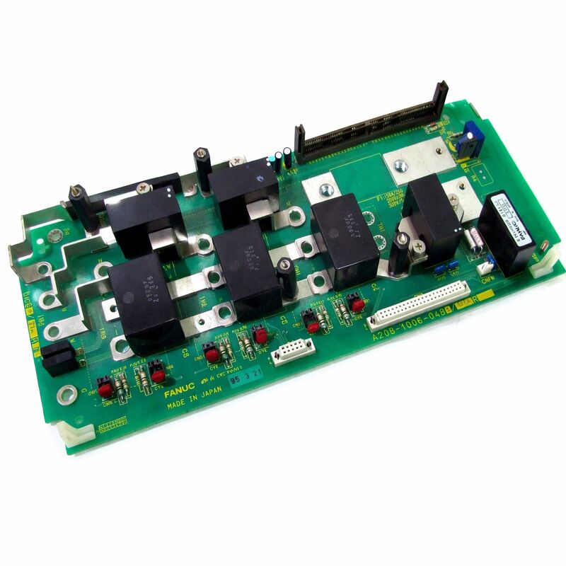
The A20B-1006-0472 is the power section PCB inside FANUC's A06B-6087-H137 PSM-37 Alpha Power Supply Module. Inside the 150mm-wide PSM-37, two boards are assembled: this power board and the A16B-2202-0424 control card. The control card manages monitoring, regulation feedback, and alarm logic. The A20B-1006-0472 is where the high-current conversion takes place — it carries the three IGBT modules that form the active rectifier stage, the DC bus capacitors, and the current and voltage sensing circuits that feed back to the control card.
In FANUC's Alpha shared-bus drive architecture, one PSM supplies the DC bus for all connected servo and spindle amplifier modules simultaneously. The PSM draws three-phase AC, converts it to a regulated 283–325V DC bus, and manages that bus continuously — protecting it from overvoltage when regenerated braking energy exceeds what other modules can absorb, and from undervoltage during peak motoring demand.
The IGBT active rectifier is what distinguishes the PSM from a passive diode rectifier design. The three IGBTs on the A20B-1006-0472 control the input current waveform, achieving near-unity power factor and allowing regenerative braking energy to be returned to the AC supply rather than dissipated in braking resistors. This is the core efficiency advantage of the PSM architecture.
Key Specifications
| Parameter |
Value |
| Part Number |
A20B-1006-0472 |
| Compatible Module |
A06B-6087-H137 (PSM-37) |
| Output |
43 kW |
| DC Bus |
283–325V |
| AC Input |
200–230V, 3-phase, 150A |
| IGBTs |
3 (active rectifier) |
| Width |
150 mm |
| CNC |
Series 16i, 18i, 21i |
Alarm Codes — Which Board Is at Fault
The PSM-37 front panel carries a seven-segment LED display showing fault codes. Before replacing the A20B-1006-0472, map the displayed alarm to the correct board:
| Alarm |
Likely Fault Source |
| AL-07 (DC bus overvoltage) |
IGBT switching failure — power board (A20B-1006-0472) |
| AL-02 (cooling fan stopped) |
Fan failure — not the power board |
| Communication faults |
Control card (A16B-2202-0424) |
| Thermal sensor alarms |
Control card (A16B-2202-0424) |
AL-07 with normal system load and no heavy motor regeneration points specifically to a power board fault — an IGBT that is no longer switching correctly and allowing the DC bus to rise unchecked. Do not reset and resume — an uncontrolled DC bus voltage rise can damage connected SVM and SPM modules
FAQ
Q1: PSM-37 shows AL-07 (DC bus overvoltage) persistently. Normal load, no heavy regeneration. Is this the power board?
Yes. AL-07 under normal conditions points to an IGBT in the active rectifier stage no longer switching correctly — the DC bus rises unchecked because the control loop can no longer regulate it. This is a power board fault on the A20B-1006-0472. Do not reset and resume — replace or repair the PSM-37 module before returning to production.
Q2: The PSM-37 failed suddenly after a brief power outage. What should be inspected?
Check the main fuses inside the PSM-37 first — a voltage transient during the outage may have blown them cleanly. If fuses are intact, the IGBTs or surge suppression devices on the power board may have failed from the transient. Fuse replacement alone is insufficient if component damage has occurred; the module requires professional evaluation before returning to service.
Q3: Can the IGBT modules on the A20B-1006-0472 be replaced individually?
Yes — IGBT module replacement as a repair service is available from specialist FANUC drive repair companies. The specific IGBT module type can be identified from the component markings on the board. After fitting a new module, gate drive circuit testing is required and the replacement must be correctly thermally bonded to the heatsink. This is a board-level repair that requires proper equipment and expertise.
Q4: Is the PSM-37 adequately sized for two SPM spindle modules and four SVM servo modules?
Calculate the combined peak current draw of all connected modules during simultaneous acceleration. The PSM-37 provides 43 kW continuous. If the combined peak demand approaches or exceeds this, the PSM is undersized and either a higher-rated PSM is required or the machine's acceleration rates must be reduced to limit peak current draw.
Q5: Is a PSM-37 from a decommissioned machine worth salvaging as a spare?
Yes, if condition is assessed before trusting it in production. Inspect the IGBT modules for thermal stress marks or mechanical damage. Measure the DC bus capacitors' capacitance and ESR if test equipment is available. A module from a machine retired due to obsolescence rather than drive failure may be in excellent condition and suitable for extended further service.

 Your message must be between 20-3,000 characters!