FANUC A20B-1006-0483 | Alpha Series PSM Drive Control PCB — DC Bus Management and CNC Interface
The Intelligence Inside the Alpha PSM
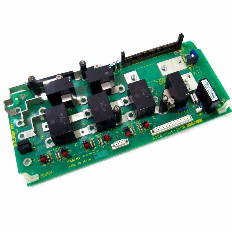
The A20B-1006-0483 is the control PCB for the FANUC Alpha series Power Supply Module — the board that handles all of the PSM's intelligent functions. The PSM itself is the foundation of the Alpha drive system: it rectifies incoming three-phase AC and creates the shared DC bus from which all the servo and spindle amplifier modules draw their motor drive power. The control PCB on the A20B-1006-0483 manages every stage of this process.
At power-on, the board runs the precharge sequence — gradually charging the bus capacitors to limit inrush current, then commanding the main contactor to close once the bus has reached operating voltage. During machine operation, it monitors the DC bus voltage continuously. When motors decelerate and return regenerative energy to the bus, the board manages this energy: either returning it to the AC supply through the active regeneration circuit or routing it to a discharge resistor to prevent the bus voltage from rising to damaging levels.
The board also manages the PSM's communication interface to the CNC controller — reporting bus status, fault conditions, and ready states that the CNC uses to sequence axis enable.
Replacing this control PCB is the targeted maintenance action when a PSM develops a control fault. The PSM's power stage (rectifier bridge, capacitors, contactor) may be entirely healthy while the control board is the failure point.
Three Fault Patterns — Which Circuit Has Failed
| Symptom | Likely Failed Circuit |
|---|
| DC bus alarm at every power-on, confirmed good capacitors and AC input | Precharge circuit or DC bus voltage measurement |
| Repeated PSM communication errors, DC bus stable during machining | CNC interface circuit |
| Recurring overvoltage trips during rapid axis deceleration | Regenerative energy management circuit |
Matching the symptom to the circuit helps confirm the control board is the correct diagnosis before ordering. A single overvoltage trip from heavy regenerative braking may indicate drive sizing vs load mismatch rather than a board fault — recurrent trips under normal operation point to the board.
Key Specifications
| Parameter | Value |
|---|
| Part Number | A20B-1006-0483 |
| Series | A20B-1006 |
| Type | PSM Control PCB |
| Application | FANUC Alpha servo drive system |
| Origin | Japan |
Suffix Matching Is Mandatory
The A20B-1006 series covers PSM control boards across the full Alpha PSM range — PSM-15, PSM-26, PSM-30, PSM-37, PSM-45, and PSM-55. Each model has its specific board variant. The -0483 suffix is matched to the control parameters and protection thresholds of its designated PSM model. A board from a different PSM model may physically fit but will produce incorrect operation. Always match the installed board's complete part number.
FAQ
Q1: The machine shows a DC bus alarm at every power-on attempt. AC input is correct and capacitors are not damaged. Could this be the A20B-1006-0483?
Yes. A persistent bus alarm with confirmed good capacitors and correct AC input points to the precharge circuit or the DC bus voltage measurement circuit on the control board. The board may not be completing the precharge sequence, or the voltage measurement circuit is reading incorrectly and triggering a false alarm. Replace the board if visual inspection shows no damage but the fault persists.
Q2: The PSM powers on normally but shows repeated communication errors with the CNC during machining. The DC bus looks stable.
Communication errors with a stable DC bus point to the board's CNC interface circuit rather than the power control functions. Check the communication cable between PSM and CNC first — an intermittent cable contact produces identical symptoms to a failed interface circuit. If the cable is confirmed good, replace the control board.
Q3: After heavy regenerative braking, the PSM tripped on overvoltage once. It cleared on power cycle and the machine seems normal. Is the board faulty?
A single trip from an unusually heavy deceleration event is not necessarily a board fault — it may indicate the deceleration load exceeded the PSM's rated regenerative capacity. If overvoltage trips become recurring under normal operating conditions, evaluate the regenerative management circuit on the control board. Also check the DC bus capacitors — repeated overvoltage events accelerate capacitor degradation over time.
Q4: Does the PSM control board store parameters that need to be transferred during replacement?
Alpha series PSM control boards typically do not store user-adjustable parameters — function is determined by the board's hardware design. No software transfer is required for most configurations. After replacement, run a full system test to confirm correct precharge behaviour, DC bus regulation, and regeneration management before returning the machine to production.
Q5: How is the correct A20B-1006-0483 confirmed against other A20B-1006 boards?
Read the full part number from the installed board's label — the -0483 suffix is the definitive identifier for this PSM model and hardware revision. Do not substitute a similar-looking board from a different PSM model. Physical dimensions and connector positions may appear identical between variants while the electronic function and protection thresholds differ.

 Your message must be between 20-3,000 characters!